PC104p-RPP
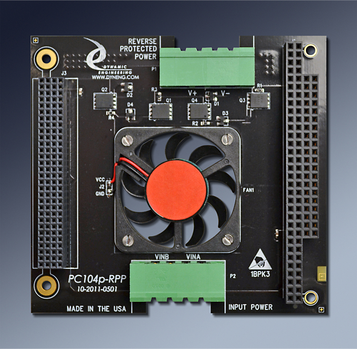
Reverse Power Protection plus Fan board
"Zero Slot Fan"™ available
Shown with fan [F] and connector options [PC104p] - mix and match connectors, fan orientations, and power source as needed

  • Reverse Power Protection operates up to 40VDC and protects your hardware.
  • FET based low power consuming design
  • Comes with mating power connectors ↣ easy connection to PC104pPWR or other power supply
  • Available in PC104, PCI-104, PC104p and Stand Alone
  • Optional Fan
  • 1 year warranty standard. Extended warranty available.
  • Extended Temperature standard.
  • ROHS and Standard processing available


Diode bridges can provide reverse power protection but do so at a high "Vforward" drop. You need the protection but the cost is lost power and generated heat. The innovative PC104p-RPP uses a combination of FET´s to steer the current providing V+ and V- from VinA and VinB. The FET´s have a much lower "Vforward". A side benefit is the voltage after the "bridge" is higher than with a standard diode arrangement. The FET´s have a lower resistive drop for both the incoming and return leg of the circuit.

Two connectors on opposite sides of the boards are used to connect to the reference system and to the power supply. On the input side the connector pins are labeled VINA and VINB. The orientation +/- or -/+ does not matter. Up to 40 VDC can be used as the FET´s have a 40 V or better reverse breakdown rating. Since the reference supply may have some noise added to the nominal value it is a good idea not to go right to the rail. On the opposite side of the board, the REVERSE PROTECTED POWER connector is labeled with V+ and V-. The V- will usually be ground. V- will be the lower of the two voltages. RPP needs approximately 6V between the rails to operate efficiently. At lower voltages the FET impedance will be higher. V+ will be within the FET drop [P channel] of the higher voltage. V- will be within the FET drop [N channel] of the lower voltage.

In the center of the board is the location for an optional Fan. The fan can be mounted to blow to the Front [default] or to the Rear [-R] direction. The Rear direction is from the primary component side toward the secondary component side to provide cooling the the board under the RPP card and throughout the stack. The Front direction will blow to the front and cool the rear side of the card above the "RPP" card in the stack. Please see PC104p-COOL for additional Fan capability without the reverse power protection. PC104p-RPP can be located directly above your stack power supply and provide cooling and reverse power protection. Since the actual voltage on the VINA/B pins is not known, +12V from the stack is used to operate the fan.

Four versions are available to meet your requirements; PC104-RPP, PC104p-RPP. PCI-104-RPP. and stand-alone. All bus and power signals are passed through the connectors chosen. For your convenience a cable is provided to interconnect RPP with PC104pPWR28 or PC104pPWR12. When working with other supplies the connectors can be reused to create the appropriate cable to your supply.

The "Zero Slot Fan"™ is designed for low height on either side of the PCB: .105" on the rear for the "BTF" model and .08" for the "FTB" model. The low profile fan used has 4.7 CFM using 12V. The fan draws 50 mA on the 12V rail.

Standard profile fans can be used in place of the low profile ones to provide more air flow, approximately 8 CFM. The standard profile fans may require a spacers within the stack.


  • 1 year warranty
  • Quantity discounts available

  • Ordering Information
  • PC104p-RPP-X Both connector positions and both fan positions filled
  • PCI-104-RPP-X PCI connector position only and both fan positions filled
  • PC104-RPP-X ISA connector position only and both fan positions filled
    X = R => blow to the rear onto the component side of the card below
    X = F => blow to the front onto the solder side of the card above [default]
    X= "not present" for no fan option selected
    Ordering RPP without the PC104, PC104p, or PCI-104 prefix will provide the RPP without the stack connectors. Please note the Fan uses stack power [12V] and will need to be supplied if used in this configuration.

    For higher velocity fans add -HV to the end of the part number. Please note : the HV fans are standard profile and will likely require an extra stack position.


    Please select your fan options and orientation below
    Install locations - fill in the direction of the air flow. The default selection is "NI" Not-installed
    Fan direction:
    F = Fan blows back to front
    R = Fan blows front to back
    Selecting HV fans will require a spacer not included
    Please select module type - PCI-104 [PCI connector only] PC104p[Both Connectors], PC104[ISA side only] Stand-Alone [no bus connectors]

    Quantity


    Manual
    You must have Adobe Acrobat to read our PDF files.

    Download the PC104p-RPP Manual in PDF format. [coming soon]


    Custom, IP, PMC, XMC, PCIe, PCI, cPCI, PC104p, VPX, VME Hardware, Software designed to your requirements


    Home | News | Search the Dynamic Engineering Site