Made in USA
The Embedded Solutions Experts
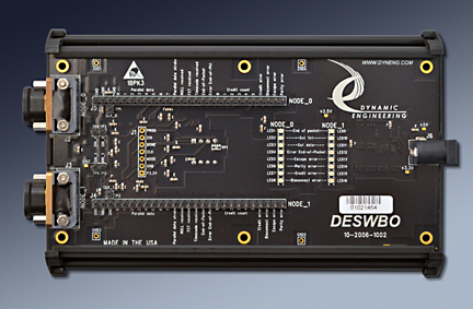
DESWBO
DESWBO will help you monitor SpaceWire Links, and solve SpaceWire connectivity issues.

DESWBO Description
- No SW required
- Self Contained Design
- 2 MDM connectors for monitoring 1 complete SpaceWire Link
- International Power Adapter included
- 1 year warranty standard. Extended warranty available.
- ROHS and Standard processing available
In A hurry? Having trouble with SpaceWire? Need to get to the bottom of your interconnect issue fast? DESWBO will help you to solve SpaceWire link issues. With DESWBO - Dynamic Engineering SpaceWire BreakOut - Spacewire can be interconnected and monitored. DESWBO has two 9-pin MDM connectors to facilitate in-line monitoring of both sides of a SpaceWire link. DESWBO is designed to detect and decode bit sequences. Signals are issued indicating what types of characters are passing between nodes as well as the contents of data and timecode characters. A running count of flow control credits for each node is calculated by the DESWBO by monitoring FCTs and N-character occurrences. LED and testpoint based user interface. Stand-alone operation. Power Supply included - now with international adapters and voltage/frequency. SpaceWire cables available.
Testimonial..."Thanks for all your help. You are right, the DESWBO was extremely helpful. It turns out our flight hardware has registers to set both the auto-null speed and the transmit speed. One problem is they were mislabeled, and we were trying to link up at 100Mb/s. We found another issue in our SpaceWire FPGA that' s causing further problems ... There's no way we would have been able to find this without the DESWBO. Once we identified these, we managed to get successful link up and transfer data in both directions"
The Dynamic Engineering SpaceWire Break-Out (DESWBO) monitors the signals of a single SpaceWire link. The board has two 9-pin MDM connectors to facilitate in-line monitoring of both sides of a SpaceWire link. DESWBO is designed to detect and decode bit sequences. Signals are issued indicating what types of characters are passing between nodes as well as the contents of data and timecode characters. A running count of flow control credits for each node is calculated by the DESWBO by monitoring FCTs and N-character occurrences.
The LVDS signals from each node are buffered to the opposite node and monitored by an FPGA. The FPGA contains the equivalent of two SpaceWire receiver modules that decode the SpaceWire signals, and extract the various data and control characters. See block diagram below. The DESWBO is tested with a special version of the PCI-SpaceWire with the ability to insert errors under software control. Normal and error conditions are tested on each unit as part of the ATP.

DESWBO Block Diagram
The end-of-packet, got-data and got-fct signals from each node are connected to pulse capture and extension circuits to drive three green LED´s. The error-end-of-packet, parity error, escape error, credit error and disconnect error signals for each node drive five red LEDs. These sixteen LED´s give a quick status of link activity and health.
In addition there are 24 test points for each node that are driven by the real-time signals from the SpaceWire character receivers, two test points for each node that are connected to the DIN and SIN signals from the LVDS receivers and one test point for each node that is driven by the recovered clock from the SpaceWire bit receivers.
The 24 test point signals consist of eight data bits, six credit count bits, Parallel data strobe, NULL received, FCT received, Timecode received, End-of-Packet, Error End-of-Packet, Credit error, Disconnect error, Escape error and Parity error. In addition there are three ground test points per node to facilitate probe grounding.
The DESWBO is powered by an external 5-volt supply [included] with on-board regulators for the various operating voltages required.
Testimonial..."Thanks for all your help. You are right, the DESWBO was extremely helpful. It turns out our flight hardware has registers to set both the auto-null speed and the transmit speed. One problem is they were mislabeled, and we were trying to link up at 100Mb/s. We found another issue in our SpaceWire FPGA that' s causing further problems ... There's no way we would have been able to find this without the DESWBO. Once we identified these, we managed to get successful link up and transfer data in both directions"
The Dynamic Engineering SpaceWire Break-Out (DESWBO) monitors the signals of a single SpaceWire link. The board has two 9-pin MDM connectors to facilitate in-line monitoring of both sides of a SpaceWire link. DESWBO is designed to detect and decode bit sequences. Signals are issued indicating what types of characters are passing between nodes as well as the contents of data and timecode characters. A running count of flow control credits for each node is calculated by the DESWBO by monitoring FCTs and N-character occurrences.
The LVDS signals from each node are buffered to the opposite node and monitored by an FPGA. The FPGA contains the equivalent of two SpaceWire receiver modules that decode the SpaceWire signals, and extract the various data and control characters. See block diagram below. The DESWBO is tested with a special version of the PCI-SpaceWire with the ability to insert errors under software control. Normal and error conditions are tested on each unit as part of the ATP.
DESWBO Block Diagram
The end-of-packet, got-data and got-fct signals from each node are connected to pulse capture and extension circuits to drive three green LED´s. The error-end-of-packet, parity error, escape error, credit error and disconnect error signals for each node drive five red LEDs. These sixteen LED´s give a quick status of link activity and health.
In addition there are 24 test points for each node that are driven by the real-time signals from the SpaceWire character receivers, two test points for each node that are connected to the DIN and SIN signals from the LVDS receivers and one test point for each node that is driven by the recovered clock from the SpaceWire bit receivers.
The 24 test point signals consist of eight data bits, six credit count bits, Parallel data strobe, NULL received, FCT received, Timecode received, End-of-Packet, Error End-of-Packet, Credit error, Disconnect error, Escape error and Parity error. In addition there are three ground test points per node to facilitate probe grounding.
The DESWBO is powered by an external 5-volt supply [included] with on-board regulators for the various operating voltages required.
DESWBO Features
Size
WxLxH 89.70mm x 147.74mm x 30.4mm measured at extreme points.
SpaceWire Ports
2 cross connected MDM-9 cable connections to provide pass through of SpaceWire signals and monitoring of both sides. Up to 180 MHz operation.
Power
5V power adapter with international voltage / plugs. Local power supplies convert to FPGA and buffer voltages.
Test Points - Error
Parity, Escape, Disconnect, and Credit error.
Test Points - Strobe
When defined control characters are received the Error End of Packet, End of Packet, Timecode, FCT, NULL, and Data strobes are pulsed
Test Points - Credit
6 positions are provided to show the current credit count on each port
Test Points - Data
The decoded data pattern is available on this section of the header for each port. 8 bits. Use Data Strobe to qualify.
Test Points - Other
SIN, DIN, and the decoded Clock are available for each port
LEDs
16 LEDs are provided. Pulses are lengthened for viewing.
Green: End of Packet, FCT, Data
Red: Error End of Packet, Escape Error, Parity Error, Credit Error, Disconnect Error.
Green: End of Packet, FCT, Data
Red: Error End of Packet, Escape Error, Parity Error, Credit Error, Disconnect Error.
Statement of Volatility
Download the Statement of Volatility for DESWBO in PDF format.
DESWBO Benefits
Speed
With the direct cross connect almost no added latency on the SpaceWire Link being monitored. Real Time decoding and monitoring of the traffic on the link.
Price
System level cost is best when reasonably priced reliable hardware is used and NRE minimized. With DESWBO system NRE is reduced for any SpaceWire connectivity issues. See directly which link is mis-behaving and how. Please check the current per item pricing with the storefront at the top of this page. Orders can be placed via the on-line ordering system or via phone / email PO order systems.
Ease of Use
DESWBO is easy to use. Jusat connect between the two SpaceWire ports to be monitored. With standard connectors and pinouts, DESWBO can be connected with standard cabling in most cases. Please download the manual for more information.
Availability
We work to keep DESWBO in stock. Send in your order and in most cases have your hardware the next day. We can ship with FedEx pick-up everyday, and other carriers as requested.
SpaceWire Specification Compatibility
DESWBO is compliant per the ECSS-E-ST-50-12C specification. All Dynamic Engineering SpaceWire Modules are compatible with DESWBO. All other SpaceWire Modules which are compliant with the ECSS-E-ST-50-12C specification can be expected to work.
Part Number: DESWBO
Ordering Options
- DESWBO Standard Product - with Power Supply and 2 ports to monitor 1 SpaceWire Link.
DESWBO Drivers
Software Support for DESWBO does not require any software to operate.
Integration support is available. Please contact Dynamic Engineering for this option or download the Technical Support Description from the Company button.
Integration support is available. Please contact Dynamic Engineering for this option or download the Technical Support Description from the Company button.
DESWBO Manuals
Click on the link to Download selected manuals in PDF format.
Download the DESWBO Manual in PDF format.
Download the DESWBO Manual in PDF format.