Made in USA
The Embedded Solutions Experts
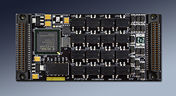
IP-OptoISO-16
IP Module 16 Optical Isolators High or Low side switch 60V, 1.5A

IP-OptoISO-16 Description
- Driver included with purchase
- Standard Type II module
- 8↔32 MHz. operation
- 16 ´Outputs´ ↣ Any combination of High Side or Low Side switches
- Fused 5V output reference
- User Frequency Input
- Diode protection
- 1 year warranty standard. Extended warranty available.
- Extended [Industrial] Temperature standard.
- ROHS and Standard processing available
IndustryPack® Modules are an important part of solutions for Embedded situations. Rugged, small, light, just right for many applications. IP-OptoISO-16 is an IndustryPack Module with 16 optically controlled FET´s [switch]. Each FET acts as a single pole normally open photovoltaic relay. The solid state approach has several advantages including bounce free operation, low on resistance, long life, fast switching, and higher reliability when compared to relays. The design utilizes a Xilinx FPGA to provide the IP interface - IDPROM, Bus interface, registers, and control for the FETs. Each optical switch has a separate bit in the control register to allow for independent operation.
The FET´s switch the Drain and Source. The Drain or Source for each switch is tied to a reference voltage. When the switches are closed the S is connected to D. The voltage range is 0-60 VDC. Each switch can handle 1.5A. The traces on the IP are rated for 1.5A. Please check with your IP carrier for maximum current capabilities. Please contact Dynamic Engineering if you need a carrier with power traces.

The Source is DIODE coupled to the Drain within the optoisolator device and DIODE coupled [100V,30A] to system ground. The DIODE´s provide protection when controlling inductive loads. Once side affect is that the Drain voltage should be the same as or higher than the Source voltage. For a high side switch the Drain side should be referenced to the system voltage and the source tied to the switched input. For a low side switch the Source should be tied to the lower voltage [usually ground] and the Drain side tied to the switch input. An external pull-up or pull-down can be used to control the level when the switch is in the off state.
IP-OptoISO-16 has a separate FET used to enable the optical side of the switch. The FET is controlled by the Xilinx and is designed to reset to the off condition to prevent potential output glitches during initialization. The enable can also be used as a master on-off mechanism by the software.
The software interface is very simple. One control bit for the Optical power enable and 16 bits to control the outputs. In addition to the output control are the timer controls. The count reference registers can be set to control the counter/timer operation.
IP-OptoISO-16 design supports an enhanced MC68230 capability with two - 32 bit counter - timers. The counter-timers are easy to use with a minimum of registers to access and complete independence. The IP clock is used as a reference; both 8 and 32 MHz can be used.
Counter/Timer A features a 32 bit down-counter with a pre-load register. The counter output is tested against a "zero" value. When zero the counter is re-loaded with the pre-load value to create a cycle. At each zero detection an interrupt can be generated. At each zero detection a waveform can be transitioned. The waveform can be enabled onto any of the outputs.

IP-OptoISO-16 Counter - Timer A Block Diagram
Counter / Timer B has a 32 bit up counter which can be cleared by the software. The counter output is masked with a user programmable value to select a particular counter bit or bits to use for interrupt creation. The counter output is also available to read via software and can serve as a real-time clock.

IP-OptoISO-16 Counter - Timer B Block Diagram
There is ample room within the FPGA to add custom state-machines etc. as your needs require.
Please contact Dynamic Engineering with any special requirements.
PCI implementations can be done with PCI3IP and PCI5IP. Applications from 1 to 80 Opto IO per PCI slot.
PCIe is supported with the PCIe3IP and PCIe5IP. Applications from 1 to 80 Opto IO per PCIe slot.
cPCI 3U is supported with cPCI2IP. Applications with 1 to 32 Opto IO per 3U cPCI slot.
cPCI 6U is supported with cPCI4IP. Applications from 1 to 64 Opto IO per 6U cPCI slot.
PC104p is supported with PC104pIP. Applications with 1 Opto IO per PC104 stack position.
PC104p situations with a custom mechanical can be done with the PC104p4IP.
Applications from 1 to 64 Opto IO per PC104 stack position.
3U VPX is supported with VPX2IP. Applications with 1 to 32 Opto IO per 3U VPX slot.
6U VPX is supported with VPX4IP. Applications from 1 to 64 Opto IO per 6U VPX slot.
The FET´s switch the Drain and Source. The Drain or Source for each switch is tied to a reference voltage. When the switches are closed the S is connected to D. The voltage range is 0-60 VDC. Each switch can handle 1.5A. The traces on the IP are rated for 1.5A. Please check with your IP carrier for maximum current capabilities. Please contact Dynamic Engineering if you need a carrier with power traces.
The Source is DIODE coupled to the Drain within the optoisolator device and DIODE coupled [100V,30A] to system ground. The DIODE´s provide protection when controlling inductive loads. Once side affect is that the Drain voltage should be the same as or higher than the Source voltage. For a high side switch the Drain side should be referenced to the system voltage and the source tied to the switched input. For a low side switch the Source should be tied to the lower voltage [usually ground] and the Drain side tied to the switch input. An external pull-up or pull-down can be used to control the level when the switch is in the off state.
IP-OptoISO-16 has a separate FET used to enable the optical side of the switch. The FET is controlled by the Xilinx and is designed to reset to the off condition to prevent potential output glitches during initialization. The enable can also be used as a master on-off mechanism by the software.
The software interface is very simple. One control bit for the Optical power enable and 16 bits to control the outputs. In addition to the output control are the timer controls. The count reference registers can be set to control the counter/timer operation.
IP-OptoISO-16 design supports an enhanced MC68230 capability with two - 32 bit counter - timers. The counter-timers are easy to use with a minimum of registers to access and complete independence. The IP clock is used as a reference; both 8 and 32 MHz can be used.
Counter/Timer A features a 32 bit down-counter with a pre-load register. The counter output is tested against a "zero" value. When zero the counter is re-loaded with the pre-load value to create a cycle. At each zero detection an interrupt can be generated. At each zero detection a waveform can be transitioned. The waveform can be enabled onto any of the outputs.
IP-OptoISO-16 Counter - Timer A Block Diagram
Counter / Timer B has a 32 bit up counter which can be cleared by the software. The counter output is masked with a user programmable value to select a particular counter bit or bits to use for interrupt creation. The counter output is also available to read via software and can serve as a real-time clock.
IP-OptoISO-16 Counter - Timer B Block Diagram
There is ample room within the FPGA to add custom state-machines etc. as your needs require.
Please contact Dynamic Engineering with any special requirements.
PCI implementations can be done with PCI3IP and PCI5IP. Applications from 1 to 80 Opto IO per PCI slot.
PCIe is supported with the PCIe3IP and PCIe5IP. Applications from 1 to 80 Opto IO per PCIe slot.
cPCI 3U is supported with cPCI2IP. Applications with 1 to 32 Opto IO per 3U cPCI slot.
cPCI 6U is supported with cPCI4IP. Applications from 1 to 64 Opto IO per 6U cPCI slot.
PC104p is supported with PC104pIP. Applications with 1 Opto IO per PC104 stack position.
PC104p situations with a custom mechanical can be done with the PC104p4IP.
Applications from 1 to 64 Opto IO per PC104 stack position.
3U VPX is supported with VPX2IP. Applications with 1 to 32 Opto IO per 3U VPX slot.
6U VPX is supported with VPX4IP. Applications from 1 to 64 Opto IO per 6U VPX slot.
IP-OptoISO-16 Features
Size
1.8x3.9 inches nominal Type II with low profile components on rear
IO
16 independent channels. Each channel has an optically isolated FET
Clocks
Compatible with 8 and 32 MHz IP bus operation. 50 MHz oscillator,
IP Decoding
Set-up for byte, word, or multiple word payload [x32, x64 etc See PCIe carriers]. LW registers are LW aligned to allow use of 32 bit accesses. ID, IO, INT, MEM spaces supported.
Memory
Spartan II - is standard and has BRAM´s to create RAM, FIFO etc.
Software Interface
Control registers are read-writeable
Windows®, Linux, VxWorks reference SW and Drivers
Windows®, Linux, VxWorks reference SW and Drivers
Interrupts
Separate enable for CTA, and CTB. Status register with current interrupt request status. Interrupts are mapped to INTR0n on IP bus. Master enable can be disabled to allow polled operation.
Power Requirement
+5V. Approximately 52 mA typical unloaded. Switched power supplied externally. Optical Isolation power of 12 mA per active channel.
Interface
The FET´s can sink up to 1.5A with a voltage range of 0-60V. Max FET on resistance = 200 milliohms, min FET off resistance 10(8) ohms. UL recognized OptoIsolation devices.
Isolation
The OptoIsolators provide 4000 Vrms I/O Isolation.
Initialization
Output channels are disabled after reset and require an explicit enable to become active.
Counter /Timer
Two independent Counter / Timer functions are provided.
CTA: 32 bit down-counter with registered initial value and auto-preload. Waveform generator. Interrupt generator based on zero detection.
CTB: 32 bit up-counter with clear and read-back. Bitwise selectable interrupt generator.
CTA: 32 bit down-counter with registered initial value and auto-preload. Waveform generator. Interrupt generator based on zero detection.
CTB: 32 bit up-counter with clear and read-back. Bitwise selectable interrupt generator.
Reliability
TBD million hours. Bellcore. GB 25c
IP-OptoISO-16 Benefits
Speed
IP-OptoISO-16 can operate with 8 and 32 MHz IP reference clocks for fast IP bus interaction. The optically isolated outputs can be controlled rapidly. The on time, and off time are approximately 1/4 mS which is rapid for this type of IO.
Price
System level cost is best when reasonably priced reliable hardware is used and NRE minimized. With IP-OptoISO-16, driver support for the carrier and IP level, reference software, history of reliable operation, and fantastic client support your cost per unit and overall costs are attractive.
Ease of Use
IP-OptoISO-16 is designed to be easy to use. Direct access to all features, aligned registers for larger access types, programmable features to allow personalization for your system. Please download the manuals and see for yourself. Reference software is provided in source form to get you started.
Availability
IP-OptoISO-16 is a stocked item.
IP Specification Compatibility
IP-OptoISO-16 is compliant per the VITA 4 - 1995 specification. Tested with PCI and PCIe based carriers. All Dynamic Engineering IP Modules are compatible with the PCIe3IP, PCIe5IP, VPXI2IP, PCI3IP, PCI5IP, cPCI2IP, cPCI4IP, PC104pIP etc. IP-OptoISO-16 will operate with any IP specification compliant carrier board.
Part Number: IP-OptoISO-16
Ordering Options
- IP-OptoISO-16 Standard board - 16 Opto Isolators , Industrial temperature components.
- -ROHS Use ROHS processing. Standard processing is ""leaded"
- -CC Option to add Conformal Coating
- -XXX See Manuals section for customized versions and replace XXX with type
IP-OptoISO-16 Drivers
Software Support for IP-OptoISO-16 includes: Windows, VxWorks, and Linux compliant drivers
The IP driver is layered and operates on top of the Carrier driver. IP drivers are auto installed for each instance detected. Please see the Driver manuals for the specifics of each type.
Drivers and Reference SW are developed for each type / version of IP-OptoISO-16 implemented. When custom versions are ordered the NRE will include providing Windows, Linux, and or VxWorks packages. For off-the-shelf models, select on the manuals tab, the Windows® and Linux SW shown is included with your purchase of the HW. A small one-time charge is required for the VxWorks versions. Unsupported SW versions may have an NRE requirement.
Integration support is available. Please contact Dynamic Engineering for this option or download the Technical Support Description from the Company button.

Reference diagam of how our Linux Driver / Application layer operate with the Carrier and IP Module.
The IP driver is layered and operates on top of the Carrier driver. IP drivers are auto installed for each instance detected. Please see the Driver manuals for the specifics of each type.
Drivers and Reference SW are developed for each type / version of IP-OptoISO-16 implemented. When custom versions are ordered the NRE will include providing Windows, Linux, and or VxWorks packages. For off-the-shelf models, select on the manuals tab, the Windows® and Linux SW shown is included with your purchase of the HW. A small one-time charge is required for the VxWorks versions. Unsupported SW versions may have an NRE requirement.
Integration support is available. Please contact Dynamic Engineering for this option or download the Technical Support Description from the Company button.
Reference diagam of how our Linux Driver / Application layer operate with the Carrier and IP Module.
IP-OptoISO-16 Manuals
Click on the links to Download selected manuals in PDF format.
IP Carrier and Module Quick Start guide for Windows®7
IP Carrier and Module Quick Start guide for Windows®10
Download the IP-OptoISO-16 Rev D Manual created Updated 9/13/16 in PDF format.
Download the IP-OptoISO-16 Windows 7 Driver Manual Rev A in PDF format. IOCTL listing and description, driver installation instructions etc.
IP Carrier Linux Manual
Linux IP Module Manual
VxWorks IP Module Manual
Download the IP-OptoISO-16 Statement of Volatility