Made in USA
The Embedded Solutions Experts
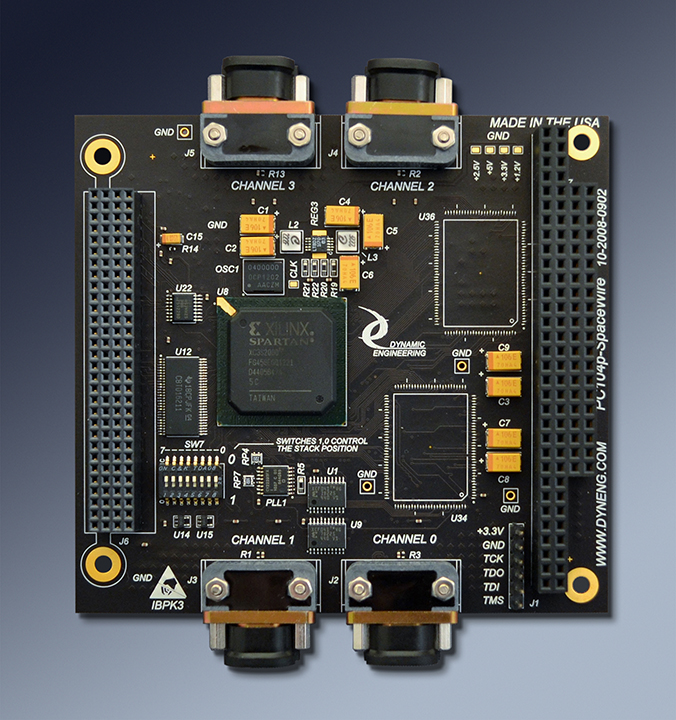
PC104p-SpaceWire
Ready for your stack

PC104p-SpaceWire Description
- Windows®, Linux, or VxWorks driver available with purchase
- 4 Ports each with DMA
- Time Code support
- Industrial Temperature
- 1 year warranty standard. Extended warranty available.
- ROHS and Standard processing available

Utilize SpaceWire to communicate with the European Space Agency and NASA equipment utilizing the ECSS-E-ST-50-12C specification. SpaceWire is configured using routers to create a hierarchical point-to-point system with high speed parallel paths.
Implement SpaceWire in a convenient PCI-104 or PC104p format. With PC104p the four ports fit within the defined connector space. The SpaceWire specification calls for LVDS signaling, and a specific 9 pin micro-D connector. Connect the PC104p-SpaceWire to other SpaceWire compliant devices without electrical interface issues.
Four fully independent and highly programmable SpaceWire ports are provided by the PC104p-SpaceWire design. In the SpaceWire implementation the ports pass tokens between two independent state-machines to provide the proper protocol. The SpaceWire protocol is advanced with link testing, error handling, command and data protocols built in. The SpaceWire electrical interface is point-to-point. With the SpaceWire protocol, it is easy to build either a hierarchical architecture system with routers or a home-run wired system. Equipment can interact with any other node in the system. PC104p-SpaceWire provides a bridge from PC104p ↔ SpaceWire. Port based DMA offloads your CPU and increases performance in your system. Time Code support provides a complete solution. Please refer to the manuals at the bottom of this page for detailed information
Each port has FIFO memory to support RX and TX functions. BK models have 16Kx32 per FIFO. K models have 1Kx32 per FIFO. Both models have an option for an additional 2x 128Kx32 FIFO. The FIFOs are 32 bits wide to optimize data transfer from the PCI/PCIe bus. The base FIFOs are internal to the FPGA and utilize dual ported RAM configured as a FIFO. Two external positions are available for larger FIFOs to be installed to support one of the channels [Rx and Tx] or two of the channels [Rx only].
SpaceWire features automatic link testing when a node is brought on line - released for operation via software. The transmitter sends NULL´s until NULL´s are received and then sends FCT´s until FCTs are received. The initial frequency is specified [ECSS-E-ST-50-12C] to be 10 MHz. Once the auto link test has passed, the hardware can switch to the programmed rate. A local oscillator is used to supply the 10 MHz reference clock for initialization. A programmable PLL is used to support operation once the link is established. The PLL is programmed via software and is referenced to the oscillator. The PLL has 4 independent clocks tied to the four channels to allow for independent rate selection. The driver supports loading the PLL from the "JED " files used to program the PLL.
SpaceWire protocol has flow control. The local memory on PC104p-SpaceWire will not overrun. In situations where the data being sent to the SpaceWire card is not buffered it is recommended to use a "-128" model with large FIFO´s on channel 0. The issue is upstream - if there is an unbuffered or under-buffered data source that will loose data if the link is throttled back the larger FIFO´s will help. The larger FIFO´s will provide more room to accumulate data if the system is not ready to allow the PC104p-SpaceWire to DMA transfer it immediately. The DMA transfers are higher bandwidth than the SpaceWire transfers allowing the system to catch-up once the DMA transfers restart. At 100 MHz and 80% data transfer the 128Kx32 FIFO will provide about 52 mS of data storage. The host would have to ignore the PC104p-SpaceWire interrupt requests for longer than 52 mS before throttling would occur. In most systems this is sufficient time to stay out of the throttled mode. To unload a full FIFO with DMA running it will take 128K/33M = .4mS => the unload to load multiplier is stongly in favor of the host side allowing the host to catch-up to the SpaceWire link once the delaying event has passed.
The interface is optimized to minimize the latency on the PCI bus. Using DMA the SpaceWire traffic is stored locally to "feed" the transmitter or store data from the receiver. The data across the link happens at the programmed rate. WIth DMA the data across the PCI bus happens at the max bandwidth of the bus with the FIFO´s providing the rate matching. Each port has FIFO memory with 4 Kbytes TX and 4K bytes RX standard and up to 512K bytes as an option. The FIFOs are 32 bits wide to optimize data transfer from the PCI bus. The base FIFO´s are internal to the FPGA and utilize dual ported RAM configured as a FIFO. Two external positions are available for larger FIFO´s to be installed to support one of the channels in both directions or two of the channels in one direction.
The programmable FIFO flags are supported for interrupt driven or polled operation. Programmable Almost Full, Programmable Almost Empty, plus Full, Half Full, and Empty. The programmable flags can be set to any debth to allow the software a programmable delay from event to empty or full. The interrupts can be very useful when sending or receiving messages larger than the FIFO size. For small messages, or command and control situations using the polled or interrupt driven modes makes sense. For larger transfers it is recommended to use the built in DMA path which self regulates the traffic eliminating the need for dealing with the interrupts other than the DMA completion interrupt. The DMA size can be much larger than the FIFO size to allow long "hands off" transfers. Your CPU can be busy with other processing instead of handling a lot of interrupts when DMA is used. The independent DMA per channel architecture makes this possible.
Dynamic Engineering Drivers are supplied with reference application software. The reference application software includes a complete test suite for the internal and external functions of the card and in some cases added features like board-to-board loop testing. The reference software is provided in source form so you can "copy and paste" into your application for a running start.
PC104p-SpaceWire is supported with the DESWBO Dynamic Engineering SpaceWire BreakOut tool for debugging SpaceWire systems, cables, and DESWCB Dynamic Engineering SpaceWire Connector Board which provides a SpaceWire Cable to system cable interface.
If your situation demands a custom application then we will update the Xilinx FPGA. Send us your timing and we will send you the interface. email us your wish list or call today!
PC104p-SpaceWire Block Diagram

The standard timing uses the data and strobe to transmit and to receive the data. The data is transmitted as a command or data. The strobe provides the transitions for clocking when the data is unchanged between adjacent bit times.
PC104p-SpaceWire Standard Timing

Implement SpaceWire in a convenient PCI-104 or PC104p format. With PC104p the four ports fit within the defined connector space. The SpaceWire specification calls for LVDS signaling, and a specific 9 pin micro-D connector. Connect the PC104p-SpaceWire to other SpaceWire compliant devices without electrical interface issues.
Four fully independent and highly programmable SpaceWire ports are provided by the PC104p-SpaceWire design. In the SpaceWire implementation the ports pass tokens between two independent state-machines to provide the proper protocol. The SpaceWire protocol is advanced with link testing, error handling, command and data protocols built in. The SpaceWire electrical interface is point-to-point. With the SpaceWire protocol, it is easy to build either a hierarchical architecture system with routers or a home-run wired system. Equipment can interact with any other node in the system. PC104p-SpaceWire provides a bridge from PC104p ↔ SpaceWire. Port based DMA offloads your CPU and increases performance in your system. Time Code support provides a complete solution. Please refer to the manuals at the bottom of this page for detailed information
Each port has FIFO memory to support RX and TX functions. BK models have 16Kx32 per FIFO. K models have 1Kx32 per FIFO. Both models have an option for an additional 2x 128Kx32 FIFO. The FIFOs are 32 bits wide to optimize data transfer from the PCI/PCIe bus. The base FIFOs are internal to the FPGA and utilize dual ported RAM configured as a FIFO. Two external positions are available for larger FIFOs to be installed to support one of the channels [Rx and Tx] or two of the channels [Rx only].
SpaceWire features automatic link testing when a node is brought on line - released for operation via software. The transmitter sends NULL´s until NULL´s are received and then sends FCT´s until FCTs are received. The initial frequency is specified [ECSS-E-ST-50-12C] to be 10 MHz. Once the auto link test has passed, the hardware can switch to the programmed rate. A local oscillator is used to supply the 10 MHz reference clock for initialization. A programmable PLL is used to support operation once the link is established. The PLL is programmed via software and is referenced to the oscillator. The PLL has 4 independent clocks tied to the four channels to allow for independent rate selection. The driver supports loading the PLL from the "JED " files used to program the PLL.
SpaceWire protocol has flow control. The local memory on PC104p-SpaceWire will not overrun. In situations where the data being sent to the SpaceWire card is not buffered it is recommended to use a "-128" model with large FIFO´s on channel 0. The issue is upstream - if there is an unbuffered or under-buffered data source that will loose data if the link is throttled back the larger FIFO´s will help. The larger FIFO´s will provide more room to accumulate data if the system is not ready to allow the PC104p-SpaceWire to DMA transfer it immediately. The DMA transfers are higher bandwidth than the SpaceWire transfers allowing the system to catch-up once the DMA transfers restart. At 100 MHz and 80% data transfer the 128Kx32 FIFO will provide about 52 mS of data storage. The host would have to ignore the PC104p-SpaceWire interrupt requests for longer than 52 mS before throttling would occur. In most systems this is sufficient time to stay out of the throttled mode. To unload a full FIFO with DMA running it will take 128K/33M = .4mS => the unload to load multiplier is stongly in favor of the host side allowing the host to catch-up to the SpaceWire link once the delaying event has passed.
The interface is optimized to minimize the latency on the PCI bus. Using DMA the SpaceWire traffic is stored locally to "feed" the transmitter or store data from the receiver. The data across the link happens at the programmed rate. WIth DMA the data across the PCI bus happens at the max bandwidth of the bus with the FIFO´s providing the rate matching. Each port has FIFO memory with 4 Kbytes TX and 4K bytes RX standard and up to 512K bytes as an option. The FIFOs are 32 bits wide to optimize data transfer from the PCI bus. The base FIFO´s are internal to the FPGA and utilize dual ported RAM configured as a FIFO. Two external positions are available for larger FIFO´s to be installed to support one of the channels in both directions or two of the channels in one direction.
The programmable FIFO flags are supported for interrupt driven or polled operation. Programmable Almost Full, Programmable Almost Empty, plus Full, Half Full, and Empty. The programmable flags can be set to any debth to allow the software a programmable delay from event to empty or full. The interrupts can be very useful when sending or receiving messages larger than the FIFO size. For small messages, or command and control situations using the polled or interrupt driven modes makes sense. For larger transfers it is recommended to use the built in DMA path which self regulates the traffic eliminating the need for dealing with the interrupts other than the DMA completion interrupt. The DMA size can be much larger than the FIFO size to allow long "hands off" transfers. Your CPU can be busy with other processing instead of handling a lot of interrupts when DMA is used. The independent DMA per channel architecture makes this possible.
Dynamic Engineering Drivers are supplied with reference application software. The reference application software includes a complete test suite for the internal and external functions of the card and in some cases added features like board-to-board loop testing. The reference software is provided in source form so you can "copy and paste" into your application for a running start.
PC104p-SpaceWire is supported with the DESWBO Dynamic Engineering SpaceWire BreakOut tool for debugging SpaceWire systems, cables, and DESWCB Dynamic Engineering SpaceWire Connector Board which provides a SpaceWire Cable to system cable interface.
If your situation demands a custom application then we will update the Xilinx FPGA. Send us your timing and we will send you the interface. email us your wish list or call today!
The standard timing uses the data and strobe to transmit and to receive the data. The data is transmitted as a command or data. The strobe provides the transitions for clocking when the data is unchanged between adjacent bit times.
PC104p-SpaceWire Features
Size
Standard dimension PC104p or PCI-104 card - 3.550in x 3.775in
Transmit Speeds
10 MHz initial rate per SpaceWire Specification. Software selectable secondary rate for transmit channel. Max. [K]frequency currently 180 Mhz. Oscillator and programmable PLL combined for user frequency support.
PCI Speed
Standard 33 MHz. operation. DMA support or standard R/W operations, DMA is independent per port - each port has a separate controller to allow long data transfers with minimal CPU overhead and increased performance.
PCI Access Width
Standard 32 bit operation supported
Software Interface
PC104p registers are read-writeable. Transmit and Receive functions separated.
Interrupts
Transmit and Receive state-machines, FIFO Programmable almost empty [transmit] and programmable almost full [receive] have programmable interrupts. Status can be polled for non-interrupt driven operation as well. Time Code interrupt.
Signaling
LVDS interface devices are utilized.
IO Interface
Available via the 9 Pin MDM connectors as specified in ECSS-E-ST-50-12C. The differential IO is properly routed with controlled impedance, and matched lengths on each of the pairs.
Interface
ECSS-E-ST-50-12C specification compliant. Time Code supported.
Specification
PC104p specification compliant
Power
5V and 3.3V from PC104p connector with 2.5V, 1.2V converted with on-board regulators.
Memory
Separate FIFOs are provided for TX and RX of each channel. Internal Block RAM creating 4K[K model] 64K[BK model] is standard for all channels. 2x128K x 32 is available on port 0. Add -128 to part number for this option -128RX uses the external FIFOs for port 0 and port 1 RX path.
Statement of Volatility
DIP switch
An 8 position switch is available to select stack position plus allow for configuration control, multiple PC104p SpaceWire boards, and to facilitate integration
STEP
STEP files are available to support your system integration. Please contact sales@dyneng.com for this option.
PC104p-SpaceWire Benefits
Speed
PC104p-SpaceWire is optimized for serial interfacing requirements. The FIFO memories and programmable interrupts off-load the CPU from most of the management other implementations require. FIFO access is optimized for the PCI bus further reducing overhead by speeding up the data transfer. On the IO side the PC104p-SpaceWire has independent and interconnected port functions. All ports can operate at maximum rate in parallel.
Price
PC104p-SpaceWire is available off-the-shelf at a reasonable price. Custom versions can also be arranged. PC104p SpaceWire is easily programmed to implement new functions. Previously implemented "custom designs" are available too. Without the costs of schematic level design, layout, debugging etc. A modified SpaceWire will represent a large cost and time savings in your budget.
Ease of Use
PC104p-SpaceWire is easy to use. Make use of our drivers for automatic detection, initialization, setting frequecies, transferring data etc. Built in loop-back capabilities and reference software help with integration into your system. Windows® Linux and VXWorks driver(s) available.
Availability
Dynamic Engineering works to keep PC104p-SpaceWire in stock. Send in your order, and in most cases have your hardware fast. With custom designs a few weeks of design is usually required. We can support immediately with the std version, then send updated FLASH files later to help get your project going - right away.
Size
PC104p-SpaceWire is a standard single height PC104p card, and meets the PC104p mechanical specifications. PC104p-SpaceWire can be used in all PC104p positions [universal voltage]
PC104p Compatibility
PC104p-SpaceWire is PC104p compliant per the PC104-Plus specification.
PCI Compatibility
PC104p-SpaceWire is PCI compliant. You can develop with a PCI (e) to PC104p adapter - PCI2PC104p, PCIBPC104pET etc.
Part Number: PC104p-SpaceWire
Ordering Options
-
Order combinations of the options by simply adding the extension(s) to your order request.
PC104p-SpaceWire -BK - with 64Kb FIFO per port (Rx and Tx separately), standard SpaceWire [ECSS-E-ST-50-12C] timing and protocol. Independent DMA and Timecode support. Four ports . ISA connector installed. ISA connector is pass through only.
PCI-104-SpaceWire-BK - with 64Kb FIFO per port (Rx and Tx separately), standard SpaceWire [ECSS-E-ST-50-12C] timing and protocol. Independent DMA and Timecode support. Four ports . ISA connector not installed.
PC104p-SpaceWire - Original memory map [legacy model] with 4Kb FIFO per port (Rx and Tx separately), standard SpaceWire [ECSS-E-ST-50-12C] timing and protocol. Independent DMA and Timecode support. Four ports . ISA connector installed. ISA connector is pass through only.
PCI-104-SpaceWire - Original memory map [legacy model] with 4Kb FIFO per port (Rx and Tx separately), standard SpaceWire [ECSS-E-ST-50-12C] timing and protocol. Independent DMA and Timecode support. Four ports . ISA connector not installed.
-128 - Add 512K [128K x 32] FIFOs to port 0 [TX and RX]
-128RX - Add 512K [128K x 32] FIFOs to port 0 and port 1 on RX
-Monitor - Add 512K [128K x 32] FIFOs to port 0 and port 1, Change FLASH to Monitor function to capture data streams on Ports 0,1. Application manages HW and stores data to file. Each packet is pre-pended with time tag, packet number and size.
-CC - add Conformal Coating
-ROHS - add ROHS processing
PC104p-SpaceWire Drivers
Software Support is supplied in the form of Windows, Linux, and VxWorks packages. The manuals are available on the SpaceWire Summary page. Windows and Linux are included in purchase. VxWorks requires an additional fee.