Made in USA
The Embedded Solutions Experts
PCIeBPMC
PCIe adapter for PMC


PCIeBPMC Description
- Industrial Temperature
- PCIe 1 Lane Interface
- PMC position with PCI interface supporting PCI [32/33 <=> 64/66]
- Plug and Play operation
- Local Power Supply for 3.3, 5 and -12V Operating from System +12V
- 1/2 Length PCIe Card
- "Zero Slot Fan"™ Compatible
- Bezel I/O and Jn4 I/O for PMC
- 1 Year Warranty Standard. Extended Warranty Available.
- ROHS and Standard Processing Available

Now you can use your PMC with a new PC. The new PC´s have PCI Express connectors in larger quantities than PCI slots. The PCIeBPMC ( PCIe Bridge PMC 1 slot) adapter / carrier converter card provides the ability to install one PMC card into a standard PCIe (Express) 1+ lane slot. Suitable for PCI operation with the PMC; 32 bit or 64 bit data and PCI (25, 33, 50, 66) MHz. clock. Auto selected or switch programmable speeds. The bridge can operate with 1 or more lanes active, and can be installed into slots with more than 1 lanes if desired.
Why the Tsi384 instead of the PEX8114? Most current PCIe carriers for PMC are using the PLX PEX8114 device. The Tundra Tsi384 provides significantly better performance. For the details request the Tundra speed comparison document [from Tundra]. It is a confidential document so we can´t reprint the results here.
We can tell you that we ran more than 100K DMA loop-tests using the PMC BiSerial III MDS1 as a test bench. We ran the test for 54 hours and could have left it longer.... The DMA loop uses a message size of 1Mb, significantly larger than the 1K x 32 FIFO within the MDS1 design. HW moves the data between FIFO´s. DMA moves the data back again. The FIFO´s are relatively small when compared to the file size being transferred. The TX and RX side have independent DMA controllers on the MDS1. There are 4 channels per MDS1. The hardware starts transferring the RX side as soon as there is data in the RX FIFO. The result is that data is being transferred in both directions using DMA across the PCIe bus. The transfers will be somewhat asynchronous to each other creating all possible conditions when allowed to run for an extended period of time.
The hardware ran Friday - Monday without error. The test operates faster than in a standard PCI slot. When you do the math an impressive amount of data was transferred and checked [4+ MLW/S]. The transfer rate is limited by the external IO rate in this case. With standard PMC [PCI 32/33] approximately 16 MLW/s can be sustained. With the local HW set to 50 MHz more than 20 MLW/S
Faster, lower powered, less complex power supply requirements, higher MTBF. In short, a better product. We use PLX devices on a number of our designs. In this case the Tundra part is superior. If you care about performance, when comparing PCI Express carriers check for the Tsi384 bridge.
The PMC user IO connector Pn4 is available on a SCSI II connector. The Pn4 "user IO" is routed differentially with matched length and impedance control to the SCSI connector. The PMC front panel connector is mounted though the PCIe mounting bracket.
For superior performance, PCIeBPMC has dual cooling cutouts for increased airflow to the PMC. If your application requires a fan you can order PCIeBPMC-FAN to have a fan(s) mounted to your PCIBPMCX1. The FAN positions are numbered 1-2 with 1 closest to the PCIe Bezel [left edge in the picture above]. Both fan positions can be mounted. Both positions are in "legal" PMC locations and can have a "Zero Slot Fan"™ mounted where the fan does not take any extra slots. Higher volume fans can be rear mounted and potentially require an extra slot.
The PCIe bus is interconnected to the PMC via a bridge. The bridge can operate with 1, 2, 3 or 4 lanes in operation. Only lane 0 is connected on the PCIeBPMC design. For 4 lane PCI-X speed capability use the PCIeBPMCX1. LED´s are provided to indicate the Lane status. The Secondary side of the bridge can operate with 32 or 64 bit data PCI . The design uses a DIPSWITCH to allow selection of auto or force on the clocks. With Auto the PMC PCIXCAP and M66En signals are used to determine the clock speed. With Force, the DIPSWITCH is used to select the clock rate. The buffering within the bridge will take care of the rate and data matching. The local side can also operate at 66 or 33 MHz depending on the PMC´s installed.
The voltage definitions are buffered between the PCIe and PMC buses. PCIe is fixed LVDS levels, and the PMC VIO is set to 3.3V.
The bridge is located near the PCIe "gold fingers" and routed with PCIe specification compliant traces for impedance and length to insure maximum performance from your Express system.
The -12V, 5V, and 3.3V for the PMC are regulated on board. The power supply designs utilize switching regulators controlling a MOSFET to convert 12V. An LC filter insures clean power at the PMC. The bridge uses a small amount of 3.3 plus 1.2V which are supplied by the PCIe 3.3V supply. The PCIe gold fingers are rated for 1.1A each, and a total of 5.5A on the +12V rail. 55W are available to the card after power conversion. Please note this is the combined power requirement across the +12, -12, +5, and 3.3V power used by the PMC. In most cases 55W is sufficient. PCIeBPMC has a cable connector to allow additional 12V power to be added to the card. The two supplies are DIODE coupled. In some cases the 12V supply on the backplane will not be adequately routed by the PC causing voltage sag on the 12V. If this occurs use the cable connector to compensate.
The power supplies include the bulk capacitance to properly bipass the FET´s and post conversion voltage rails. In addition the PMC connectors are bipassed with a .1 uF capacitor at each power pin. The power supplies are checked with voltage monitor circuits. The LED´s are not illuminated unless the voltage is within the defined range.
The individual pins on the JN4 (PN4) connectors for each slot are accessible by a 68 pin SCSI connector. We recommend using our SCSI cable and the HDEterm68 breakout block with the SCSI connector.
The PMC JTAG connections are routed to a header. The header is configured to for discrete connections. Please add -JTAG if you want the header installed on your PCIeBPMC.
PCIeBPMC Features
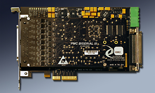
PCIeBPMCX1 [4 lane model] shown loaded with a Dynamic Engineering PMC BiSerial III Module
Size
1/2 size PCIexpress card with 1 lane interconnected to the Bridge. Single lane operation. 1+ lane connector compatible.
PMC compatible slots
1 PMC position provided. DMA capable
Clocks
PCI secondary bus can operate at PCI(66, 50, 33,25) MHz. User switch or automatic selection clock selection.
PMC VIO
3.3V
Software Interface
Industry Standard TSI384 Bridge register definitions. The bridge does not require any user set-up. PMC register definitions as defined by installed hardware. For superior DMA perfomance some Bridge settings should be enhanced. Dynamic Engineering Drivers [Linux and Windows] have this feature. Ask and we can share the registers, offsets and new values.
Power
Local power supplies provide +5(9.5A), +12, -12V(4A), +3.3V(9.5A) available to PMC´s with adequate +12V input current. Supplies use industrial temperature components, and spreading power planes to manage the thermal load. It is recommended to use the FAN option for high power requirement PMC´s. User selectable power supply enable{on/off, delayed, not delayed] for 3.3V and 5V supplies.
3.3V and 5V power supplies capable of up to 9.5A continuous without additional cooling in lab environment. Adding a fan to position 2 reduces the temperature significantly - approximately 50 degree's C allowing for a wider operational temperature range. The max FET temperature was below 100C for the non-fan case and mid to upper 40´s for the fan installed case. The max junction temperature of the FET is 150C. We used a case temperature limit of 100C to be conservative. A
3.3V and 5V power supplies capable of up to 9.5A continuous without additional cooling in lab environment. Adding a fan to position 2 reduces the temperature significantly - approximately 50 degree's C allowing for a wider operational temperature range. The max FET temperature was below 100C for the non-fan case and mid to upper 40´s for the fan installed case. The max junction temperature of the FET is 150C. We used a case temperature limit of 100C to be conservative. A
midpointof 7.44A on 5V and 6.6A on 3.3V produced 65.8C on the 5V FET with no cooling [3.3V FET was 57.6C]. We can estimate that the card can handle the given load up to 50C with some margin. With lighter loads higher temperatures can be achieved without cooling. With cooling higher loads can be achieved at higher temperatures.
Thermal
PCIeBPMC has cut-outs to support increased airflow over the PMC´s component side. Optional fan(s) with two mounting positions per PMC position are available and recommended for many applications. Industrial Temperature components.
Interrupts
INTA, INTB, INTC, INTD routed to to Bridge and handled per PCIe convention. Most PMC´s use one Interrupt level [INTA].
IO Interface
PMC Bezel IO supported at PCIe bracket. Jn4 "user IO" Differential, Impedance controlled, matched length traces from Jn4 to SCSI connector.
Specification
PMC, PCI, and PCIe specification compliant
LED´s
+3V, +5V, +12V, -12V[with voltage monitoring] and Busmode 1 [present], PCIe Lane Status [4]
JTAG
PMC JTAG connections are tied to a labeled header. Add -JTAG to part number for this option to be installed.
Statement of Volatility
Reliability
25C GB 1,714,065 Hrs. [conservative value]
Export Classification
EAR99, HTS:8537.10.9050
PCIeBPMC Benefits
Speed
PCIeBPMC offers PCI speeds at the PMC position
Price
Make use of existing PMC designs in PCIe applications without paying for the expense of a new design and layout. Quantity discounts are available.
Ease of Use
PCIeBPMC is easy to use. A plug and play interface to the PMC site. The Bridge can be configured with the user switch on board. PCIeBPMC is a Transparent Bridge. In most cases the switches can be left with the factory settings. The manual contains clear directions for switch options. Dynamic Engineering has developed routines for Windows and Linux applications to set the Bridge to an optimal configuration for DMA. Please contact Dynamic Engineering for the code to add to your system.
Availability
PCIeBPMC is a popular board. We keep the default models in stock. We pre-build with the common devices installed, and then cllientize to your specific configuration. This method allows faster delivery on our more popular products while retaining the ability to have multiple client options.
Size
PCIeBPMC is a 1/2 size PCIe board which conforms to the PCIe mechanical and electrical specifications. Eliminate mechanical interference issues. PCIeBPMC can be used in all 1/2 and full length PCIe compliant slots.
PMC Compatibility
PCIeBPMC is PMC compliant per the PMC specification [compliant per the IEEE 1386]. All Dynamic Engineering PMC Modules are compatible with the PCIeBPMC. All other PMC Modules which are compliant with the PMC specification are compatible with PCIeBPMC
PCIe Compatibility
PCIeBPMC is PCIe compliant. PCIeBPMC can be expected to work in any PCIe compliant backplane with 1+ lane connectors and 1/2 or full length card positions. PCIeBPMC has been tested in multiple backplanes.
Part Number: PCIeBPMC
Ordering Options
- PCIeBPMC Standard board - Standard Build, SCSI connector standard processing.
Order combinations of the options by simply adding the extension(s) to your order request. - -FAN( ) Need additional cooling? order the PCIeBPMC-FAN() for a pre-installed 12V 5.2CFM fan(s) to maximize cooling and functionality of your card. The fan has been tested with high wattage prPMC devices.
Fan position 1 is closest to the PCI bezel. Valid Fan options include:
(1 or 1Rz) position 1 only low profile or rear mount.
(2 or 2Rz) position 2 only low profile or rear mount.
(1R) 8 CFM fan position 1 available as R mount only .
(2R) 8 CFM fan position 2 available as R mount only .
Any combination with at most 1 fan per position defined. - -ROHS Use ROHS processing. Standard processing is "leaded"
- -CC Option to add Conformal Coating
- -NC Order to receive a PCIeBPMC with no SCSI connector installed.
- -5VXXX Order to receive a PCIeBPMC with 5V supply forced to (replace XXX) No Delay [ND], Delay[DEL], Off[OFF] instead of user selectable
- -3VXXX Order to receive a PCIeBPMC with 3.3V supply forced to (replace XXX) No Delay [ND], Delay[DEL], Off[OFF] instead of user selectable
- -DDV Order the PCIeBPMC-DDV to receive a PCIeBPMC with a vertical PC style "Disk Drive" connector installed for supplemental power. The "-DDV" option will allow an added 5A [60W] to be used on the card. This version is usually used with the -NC option for high current boards in a short PCIe slot.
- -OT Order the PCIeBPMC-OT to receive a PCIeBPMC with a high power connector installed for supplimental power. Special screw terminal style positive lock connector with 20A rating. Perfect for high powered cards and or custom cable requirements. Comes with board side connector installed. Cable side connector provided to terminate your power cable. Pins1,2 = GND. Pins 3,4 = 12V. Custom cables available. Please contact Dynamic Engineering for this option.
Please note that the standard card without the -DD, -DDV, or -OT option will work in most situations. Many PMC´s fit within the "gold finger" power budget.
If you are unsure of your power requirements, we recommend ordering with a Power Connector installed to support your future development, and eliminate needing to install at a later date.
PCIeBPMC Drivers
Software Support for PCIeBPMC is not needed. PCIeBPMC has a transparent bridge, the drivers and application SW associated with the PMC will not need changing to use this carrier.
Please see the PMC Driver manual for the specifics of operating the installed device.
Please see the PMC Driver manual for the specifics of operating the installed device.