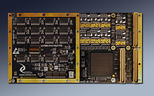
ccPMC-Parallel-TTL
Conduction Cooled PMC Format
Pictured built with TTL option
64 TTL IO in one slot with COS interrupts


Does your system require single ended TTL or CMOS level signals? How about medium speed Analog data capture [ADC 1-10 MHz]? Dynamic Engineering has a multitude of solutions covering different architectures and mezzanine types. With most architectures you have a choice with carriers for cPCI, PCI, VME, PCI-104, and other buses for both PMC and IP mezzanine modules. Usually your choice is based on other system constraints as both the PMC and IP can provide the IO you require. Dynamic Engineering can assist in your decision making regarding architecture and other trade-offs. Dynamic Engineering has carriers for IP and PMC modules for most architectures, and is adding more as new solutions are requested by our clients.

The Conduction Cooled PMC compatible ccPMC-Parallel-TTL has build options to have up to 64 independent digital IO and up to 8 ADC channels. The high density makes efficient use of precious PMC slot resources. The IO is available for system connection through the rear [Pn4] connector. The rear panel IO has a PIM and PIM Carrier available for rear panel wiring options. The HDEterm68 can be used as a breakout for the rear panel IO when the PMC carrier has a SCSI style connector for the rear IO. The HDEcabl68 provides a convenient cable. The pin definitions are consistent with the PMC Parallel IO and PMC Parallel TTL designs to enable users to migrate to the ccPMC Parallel TTL quickly and easily when a conduction cooled solution is required.

Each TTL IO is independently programmable. The outputs can be enabled and driven high or low. When disabled on-board pull-ups terminate the lines. The pull-ups can be referenced to 5V or 3.3V as an ordering option. A master enable is available to allow the user to synchronize the upper and lower outputs for coherant 64 bit operation in a 32 bit system. The master enable can be set to allow independent upper and lower bank updates.

All TTL channels can be read as inputs regardless of the transmit enable programming. Local loop-back can be used for BIT. All IO channels can be used as interrupt generators. Interrupts are programmable to be based on either or both edges for "Change of State" operation. An external clock, PCI clock, or oscillator can be selected for the reference on the COS operation. The reference can be programmed to be divided to create lower frequencies. A PLL is available to support user frequency selection to provide the right sampling rate for your application.

All of the IO are routed through the FPGA device to allow for custom applications that require hardware intervention or specific timing. For example the design of the ccPMC Parallel TTL supports internal FIFO´s and DMA. With an added state-machine for your interface the hardware can provide much more than a simple parallel interface. Contact Dynamic Engineering for convenient customer specific implementations.

The ccPMC-Parallel-TTL has an option to remove some of the TTL channels and replace them with ADC channels. The lower 32 bits can be removed and 8 - 12 bit ADC´s installed instead. Each ADC can be programmed to operate at frequencies up to 10 MHz. Options for synchronous sampling across channels and independent reference frequencies under software control. The ADC´s can be programmed for different voltage ranges with a pair of resistors. The ADC is a 0-5V model. WIth matching resistors 0-10V is scaled etc. Each ADC has a high bandwidth opamp buffer to support high frequencies with low current requirements [in the input signal]. Please contact Dynamic Engineering with your requirements.

Each of the ADC channels can be supported with memory, DMA, data/signal processing, etc. For example; The BA19 version of the ccPMC Parallel TTL has 32 TTL lines, and 8 ADC´s. Each ADC has a separate DMA channel and FIFO memory support. The data is sampled and tested against the current reference sample. When the new sample exceeds the range established by the current sample it is saved into the FIFO along with the Time Tag and used as an updated reference sample. The range is programmable [ sample - lower offset <=> sample + upper offset]. With the Time Tag a known number of in range samples occurred between the data stored. Data reduction at the source reduces CPU processing later and bus overhead. Tell us what features you require.

The base model has a simple to use register based interface. The registers are mapped as 32 bit words. All registers are read-writeable. The Windows® compatible [XP/2000] driver is available to provide the system level interface for this design. Use standard C/C++ to control your hardware or use the Hardware manual to make your own software interface. The manuals for the different implementations are available for download from the bottom of this page.

All parts are industrial temp or better [-40C <=> +85C]. Conformal coating, thermal gluing and thermal foam are available options help adapt to your environment.

conduction cooled 64 TTL or 32 TTL and 8 ADC

ccPMC-Parallel-TTL Features

  • Size
  • Single wide PMC.

  • Parallel Interface
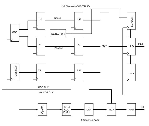
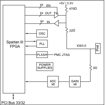
  • 64 independent TTL IO. The pull-ups can be referenced to 3.3V or 5V. Rear IO [Pn4] Unused ports isolated with resistors for "zero bus stub". Matched IO within 1/1000 inch for on-board traces.

  • Analog Interface
  • 8 independent / sychnonized ADC. 12 bit 10 MHz capable ADC´s with opamp buffers and voltage dividers. FIFO support with DMA for each channel. Signal Processing on received data or straight packed data.

  • Pull-up Resistor
  • 470 standard, 1K, 4.7K available. Double pull-ups available on digital lines

  • Sink Current
  • 64+ mA per channel on digital lines

  • Cable interface
  • Pn4 backplane connection. Your PMC carrier will specify the system connector.

  • Software Interface
  • 32 bit registers mapped to the 64 IO channels. Read-back of channel control registers and input registers. Read-write of control registers for card configuration. Direct and DMA read of ADC data.

  • Interrupts
  • All IO Channels can be programmed to cause interrupts. Each channel is programmable to be masked, rising, falling, both [COS]. Level interrupts plus DMA completion on ADC channels. Interrupts are mapped to INTA on PCI bus.

  • Power Requirement
  • +3V, +5V, and +/- 12V when ADC´s are installed.

  • Protection
  • The isolation resistor standard is 22 ohms to Pn4. Resisive coupling for current limiting and ESD protection. Other values are available.

  • COS Clock
  • Input registers are programmable to capture data with the COS clk. SW can select PLL or Oscillator as the source for clock. A programmable divider allows a wide range of sampling frequencies to be selected.

  • Custom
  • All bits are routed through the FPGA to allow for custom state-machine implementations. FIFO and Dual Port RAM can be implemented. See custom models below.


    ccPMC-Parallel-TTL Benefits

  • Speed
  • ccPMC-Parallel-TTL is a software controlled HW interface. As fast as the PCI interface can push the data across, the outputs can change. With the Windows® driver several accesses per microsecond can be achieved. Your time to market will be shortened by the easy to use interface, flexibility in design, and off-the-shelf availability. With DMA enabled and FIFO´s instantiated faster transfers can occur. Up to 48K x 32 internal FIFO can be achieved with the 4000 sized FPGA.

  • Price
  • ccPMC-Parallel-TTL has an attractive price, and low integration cost for a low system cost. ccPMC-Parallel-TTL has an associated PIM and PIM Carrier which can lead to further savings in cPCI environments.

  • Ease of Use
  • ccPMC-Parallel-TTL is easy to use. A point and shoot user interface to the IO. Please download the manual and see for yourself. The engineering kit provides a good starting point for a new user.

  • Availability
  • ccPMC-Parallel-TTL is designed to be customized. The base version is available from stock. New "clientized" versions can be dialed in quickly. We can ship a model that is " just like but different" to you right away and follow-up with new FLASH files to match your requirements. You can make a quick start having the HW available right away and adding features as they are available.

  • Size
  • ccPMC-Parallel-TTL is a standard single wide PMC [single slot] board which conforms to the PMC mechanical and electrical specifications. Eliminate mechanical interference issues.

  • PMC Compatibility
  • ccPMC-Parallel-TTL is PMC compliant per the IEEE 1386 specification. ccPMC-Parallel-TTL is also compliant with the conduction cooled PMC specification.

  • PCI Compatibility
  • ccPMC-Parallel-TTL is PCI compliant. You can develop with a PCI to PMC adapter - PCI2PMC or PCIBPMC etc..


    Engineering Kits
    Dynamic Engineering provides Engineering Kits to help our customers have a successful and quick integration. Engineering Kits will save time and money with decreased T&I. We recognize that different customers have different needs. The Engineering Kits are standardized in description to help with selection. The kits are segmented to allow for customers who only need hardware support, software support or a mixture. The Engineering Kit is highly recommended for first time buyers. The kit pricing is discounted to encourage their use.

    Please note: The options for conduction cooled PMC´s are different from standard PMC´s.
    Applications Hint: If developing for cPCI the use of the
    PIM Carrier and PIM Universal along with a SCSI cable and HDEterm68 can speed your development.

    ccPMC-Parallel-TTL-1 .......... Hardware Support Engineering Kit includes:
    Board level Schematics [PDF]

    ccPMC-Parallel-TTL-2 .......... Hardware Support plus Driver Engineering Kit includes:
    Board level Schematics [PDF], Software [PMC-Parallel-TTL Driver and sample application zip file ]

    ccPMC-Parallel-TTL Drivers.......... Software Support Only Windows®XP and 2000 compliant driver for the PMC-Parallel-TTL:
    Please see the Driver manual for the specifics of installing and using the driver. The driver includes a user application reference which we use to test the boards. The user reference software, driver, and include files make it easy to integrate the PMC-Parallel-TTL into your system. When customized versions are ordered the corresponding driver version will be sent.
    Please contact Dynamic Engineering if you would like us to produce one for your PMC or a third party design.


    Ordering Information
    Base part number: ccPMC-Parallel-____
    Primary Options:
    TTL 64 TTL no ADC
    TTL-ADC 32 TTL and 8 ADC channels
    ADC 8 ADC channels and no TTL
    Secondary Options:
    -CC to add conformal coating
    -3V to change from 5V IO reference to 3.3V IO reference

    Select Build Option, Extra Component Options and Engineering Kit Option


    Quantity

    Manual - Standard
    Download the
    ccPMC-Parallel-TTL Rev A1 Manual in Adobe Acrobat PDF format.


    Customer Special Versions & Manuals
    You can order these too or request that we design one for you

    32 TTL IO with COS plus 8 ADC in one slot
    COS with Time Stamp and 16Kx32 storage plus 8 channels of ADC 10 MHz 12 bit with
    independent DMA and storage. Unfiltered or Data compression on ADC channels with
    programmable thresholds. Programmable clock rates for COS, Time Stamp and ADC´s
    Download the
    ccPMC-Parallel-TTL-BA18 Rev A1 Hardware Manual in Adobe Acrobat PDF format.
    Download the ccPMC-Parallel-TTL-BA18 Rev A Windows® Driver Manual in Adobe Acrobat PDF format.
    Client: Boeing


    Related Products
    HDEcabl68 SCSI II/III Cable
    HDEterm68 SCSI II/III to 68 pin terminal block
    PCI2PMC adapter card
    PCIeBPMCX1 PCI Express to PMC adapter card
    PIM-Parallel-IO facilitate rear panel IO


    Try before you buy program


    Custom, IP, PMC, XMC, PCIe, PCI, VPX, VME, PCI-104 Hardware, Software designed to your requirements


    Home | News | Search the Dynamic Engineering Site