PCIBPMCX2
PCI to PMC Adapter / Carrier


PCIBPMCX2 (PCI/PCI-X Bus Compatible) Bridge based PCI and PMC Compatible Adapter Carrier
Shown With DIN Connectors
Available With SCSI Connector, Ethernet, and Serial port connectors, "Zero Slot Fans"™ and other options

Embedded applications frequently require real time processing coupled with special purpose IO. With the PCIBPMCX2´s two slots; a PrPMC can be matched with another PMC to make a high bandwidth processing node. The PrPMC can communicate with the host for set-up, and then use the local bus to control and transfer data with the special purpose IO card. For example the PMC-BiSerial-III-HW1 provides 32 channels of Manchester encoded IO, and when matched with a PrPMC can control or monitor a large system in real time.

When the carrier is reset the bridge acts as a tranparent connection from the host PCI / PCI-X bus to the PMC(s) installed. The PMC(s) can be completely controlled with the standard driver software for those modules. With additional software the bridge can be programmed to create a local address space where the interaction between the PMC´s is hidden from the system. The bridge is acting in a non-transparent mode in this case.

To support your situation; the interrupts are switch programmable to be cross connected or interact with the host computer. The PMC IO module can interrupt the PrPMC if your system is configured for local processing. Both positions can be bus masters allowing for DMA and single word transfers on the PCI bus.

PCIBPMCX2 ( PCI Bridge PMC 2 slots) adapter / carrier converter card provides the ability to install one or two PMC cards into a standard PCI/PCI-X slot. The universal voltage PCI card is suitable for PCI or PCI-X operation with 32 bit or 64 bit data and 33, 66, 100 or 133 MHz. clock. The installed PMC´s can have the primary XMC connector installed. The PCB is free of components in the area in front of Pn1 to allow for cards with XMC connectors to be installed.

PMC user IO connector Pn4 from slot 0 [rear] is brought out to one of two connectors for access (DIN IDC or SCSI II). The signals corresponding to the PrPMC standard Ethernet and Serial lines can optionally be connected to the Ethernet and Serial port connectors at the top edge of the board. The Ethernet and Serial signals are isolated from the standard IO with resistor packs to keep the unused side stub essentially zero length. The Ethernet signals are differentially routed with matched length, impedance controlled traces. Slot 1 [front] has options for the standard Pn4 IO to be connected to a DIN or SCSI connector. Please see the ordering options below.

The PMC front panel connector for slot1 is mounted though the PCI mounting bracket. Slot zero is accessable at the rear of the card.

For superior performance PCIBPMCX2 has two cooling cutouts per PMC for increased airflow to the PMC´s. If your application requires a fan you can order the -FAN option to have fans mounted to your PCIBPMCX2. The FAN positions are numbered 1-4 with 1 closest to the PCI Bezel [left edge in the picture above]. The fans are specially modified to work with our carriers. The resulting "zero slot fan"™ assembly is mounted [positions 2 and/or 3] under the PMC and PCI maximum height requirements. Positions 1 and 4 intrude into the "connector" space of the PMC. In many cases the PMC does not use the full height allowing the fans to be used in these positions too. The low profile fans can be mounted to the rear of the board in positions 1 and 4 [if required]. In many cases rear mounted fans won´t interfer with the card in the next slot. Please refer to the Fan dissussion near the ordering section for more information.

The PCI bus is interconnected to the PMC via a 64 bit 133 MHz capable bridge. The bridge allows the PCI bus to operate with different parameters than the PMC cards - for example the PCI bus can operate at 66 MHz with 64 bit data and the PMC with 33 mhz and 32 bit data. The buffering within the bridge will take care of the rate and data matching. The local side can also operate at 133, 100. 66 or 33 MHz depending on the PMCs installed. The PCIBPMCX2 can control the M66EN signal via a dipswitch setting, or the PMC can control the M66EN setting directly. The PCI-X controls are also selectable via dipswitch.

The voltage definitions are buffered between the PCI and PMC buses. The PCI VIO automatically defines the reference levels for the primary side of the bridge. A shunt is used to control a MOSFET to select which voltage reference is used on the secondary side. The voltages can be the same or different between the primary and secondary sides of the bridge. A 5V PMC card can be used with a 3.3V PCI bus and vice-versa.

The bridge insures that multiple PCIBPMCX2 cards can be installed onto the same PCI bus stub. The PCB routing between the PCI gold finger connector and the Bridge is done to meet or exceed the PCI specifications. In particular the trace lengths, loading, impedance, and proximity to planes and plane splits are carefully implemented and checked.

Local Regulation of the 3.3V power insures clean power on the 3.3V rail, and that the rail is energized. The 5V supply is routed to the 5V rail and to the local regulator. The regulator design utilizes a switching regulator controlling a MOSFET to convert 5V to 3.3V. An LC filter insures clean power at the PMC´s. A shunt allows the user to select between the PCI supply and the local regulator. The bridge uses approximately 700 mA maximum leaving 8+ amps on the 3.3V rail for the PMC´s. The bridge is properly bipassed with additional capacitors near the PMC connectors.

The 5V, +12 and -12V voltages are supplied to the PMC´s via the PCI connector. The voltages are bipassed at the PCI connector and at the PMC connectors. The 5V power has additional decoupling to support the regulator requirements.

The individual pins on the Jn4 (Pn4) connectors for each slot are accessible by either a 68 pin SCSI connector or a 64 position DIN connector. We recommend using our SCSI cable and the HDEterm68 breakout block with the SCSI connector. The industry standard VME [DIN] IDC connector is easy to connect to your system using DINterm64 which is a 64 position terminal strip and the DIN Ribbon Cable 64, a 64 position ribbon cable.

The PMC JTAG connections are routed to headers. One header is configured to match the Altera standard, and the other is set for discrete connections - Xilinx and other manufacturers. Please let us know if you want these headers installed.

Each Dynamic Engineering manufactured design including the PCIBPMCX2 is fully tested. The "ATP" runs a full suite of tests to check complete operation of the card. In the case of PCIBPMCX2 the PMC-Parallel-TTL-BA16 is used to check 32 bit PCI operation including simultaneous DMA from each slot. The IO connectors are tested with loop-back connectors and software also using the PMC-Parallel-TTL-BA16. The 64 bit modes are tested using a 64 bit memory card and doing pattern tests to check LW and byte access modes across the bus. Power supplies are tested by use and measurement. Each card is tested, documented and recorded for future access should the history of the card be required. A copy of the signed ATP can be provided if required for your QA requirements.

  • 1 year warranty
  • Quantity discounts available

  • PCIBPMCX2 Features

  • Size
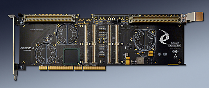
  • Full length PCI card.

  • PMC compatible slots
  • 2 PMC Slots provided.

  • Clocks
  • PCI primary bus can operate at 133, 100, 66 or 33 MHz. Secondary side can operate at the same or lower frequency than primary side. User switch provided for clock selection, or automatic detection can be used.

  • Access Width
  • Standard PCI byte lanes supported for byte, word and long access dependent on installed PMC. 64 or 32 bit operation from either bus supported by Bridge.

  • Access Frequency
  • Bridge supports 133,100, 66 or 33 MHz operation.

  • Software Interface
  • Industry Standard 31154 Bridge register definitions. The bridge does not require any user set-up. PMC register definitions as defined by installed hardware.

  • Interrupts
  • INTA, INTB, INTC, INTD routed to PCI connector from both PMC slots. Most PMC´s use one Interrupt level [INTA]. User switches allow independent mapping of the PMC interrupt request to the PCI connector. Slot 0 is usually mapped to INTA and slot 1 to INTB. In addition the interrupts can be routed [controlled with DIPswitch between the PMC positions to support local PrPMC control.

  • Power
  • +5, +12, -12V, regulated or PCI +3V supplied to PMC´s.

  • VIO
  • Primary side set by PCI bus. Secondary side set by user selection [shunt]. Regulated 3.3V or 5V via MOSFET to VIO mini-plane.

  • Thermal
  • The PCIBPMCX2 has a cut-outs to support increased airflow over the PMC component side. Optional fan(s) with 4 mounting positions are available.

  • IO Interface
  • Front Bezel IO supported at PCI bracket. Jn4 "user IO" supported with either SCSI or DIN connectors. See Panduit for mate [120-964-455] or standard SCSI II connector. Optional support for Ethernet and Serial ports from PrPMC devices.

  • Specification
  • PCI, PCI-X, PICMG 2.15 specification compliant


  • LED´s
  • +3V, +5V, +12V, -12V and Busmode 1 [present] for each slot plus VIO.

  • DIP switch
  • 4 - 8 position switchs are provided to allow for configuration control and to select the primary and secondary clocking options.

  • JTAG
  • Primary PCI JTAG connections are made to the Bridge. The PMC JTAG connections are tied to labeled headers. One header following the Altera standard and one compatible with Xilinx and other manufacturers.

  • Volatility
  • Statement of Volatility


    PCIBPMCX2 Benefits

  • Speed
  • PCIBPMCX2 offers PCI-X and PCI speeds plus a second PMC slot for designs with more than one PMC. For local processing the rear slot can be used for a PrPMC with the IO or signal processing in the front slot. The Host computer can set-up operation, and then the PrPMC can use the local bus for high speed data transfer with the second PMC.

  • Price
  • PCIBPMCX2 is competitively priced - more than a single slot carrier, and less than two carriers. Make use of existing PMC designs in PCI applications without paying for the expense of a new design and layout. Save PCI slots with two PMC´s in one location. Quantity discounts are available.

  • Ease of Use
  • The PCIBPMCX2 is easy to use. A plug and play interface to the PMC site. The Bridge can be configured with the user switches on board; eliminating any requirement for special software for the bridge itself. The PCIBPMCX2 has a bridge with Transparent and Non-Transparent modes. Standard drivers for the PMC´s can be used without any software required for the carrier. The board comes configured for a 66 MHz capable primary bus and 33 MHz secondary bus. In most cases the switches can be left with the factory settings. The manual contains clear directions for switch options. The engineering kit provides a good starting point for a new user.

  • Availability
  • The PCIBPMCX2 is a popular board. We keep the PCIBPMCX2 in stock. Send in your order and in most cases have your hardware the next day - delivered to you via FedEx.

  • Size
  • The PCIBPMCX2 is a full size PCI board which conforms to the PCI mechanical and electrical specifications. Eliminate mechanical interference issues. The PCIBPMCX2 can be used in all full length PCI compliant slots. Please check that your computer has a full length slot with the proper PCI offset card guide support.

  • PMC Compatibility
  • The PCIBPMCX2 is PMC compliant per the IEEE 1386 specification. All Dynamic Engineering PMC Modules are compatible with the PCIBPMCX2. All other PMC Modules which are compliant with the PMC specification are compatible with the PCIBPMCX2.

  • PCI Compatibility
  • The PCIBPMCX2 is PCI compliant. The PCIBPMCX2 can be expected to work in any PCI compliant backplane. The PCIBPMCX2 has been tested in multiple backplanes.


    Breakout Kit
    PCIBPMCX2-BO...............Break Out Kit includes: 3' HDEcabl68 and HDEterm68-MP
    PCIBPMCX2-BO64..........VME Break Out Kit includes : 3' HDEcabl64 and HDEterm64


    PCIBPMCX2 Ordering Information
    PCIBPMCX2 Order the PCIBPMCX2 for a base version (PCIBPMCX2-VME)

    -FAN() Need additional cooling? Order the PCIBPMCX2-FAN() for a pre-installed 12V 5.2 CFM fan(s) to maximize cooling and funtionality of your card. The fan has been tested with high wattage prPMC devices. Fan position 1 is closest to the PCI bezel, 2, and 3,are numbered from left to right. All Positions are completely legal height wise for PMC and PCI.
    Fan ordering combinations - any combination of differnet positions is valid: 1 or 1R, 2, 3 . For example -FAN23 would be standard low profile fans in positions 2 and 3. -FAN1R23R would be low profile fans in all positions with 1 and 3 rear mounted.


    -ENET Order the PCIBPMCX2-ENET to receive a PCIBPMCX2 with 2 ethernet ports installed .
    The connectors are added to work with Ethernet equipped PMC´s

    -SER Order the PCIBPMCX2-SER to receive a PCIBPMCX2 with a serial connectors installed .
    The Serial Port connectors are added to work with serial port equipped PMC´s


    -SCSI Order the PCIBPMCX2-SCSI to receive a PCIBPMCX2 with the SCSI connectors mounted for Pn4 IO.[no VME / DIN]

    -NC Order the PCIBPMCX2-NC This model has neither VME nor SCSI style connector installed.

    -VIO3 The VIO3 option removes the FET for the secondary VIO to force it to be 3.3V only.

    Contact sales@dyneng.com for price and leadtime on this product.

    Manual
    You must have Adobe Acrobat to read our PDF files.

    Download the PCIBPMCX2 Manual 10/15/07 in PDF format.

    Related Items:
    HDEcabl68 SCSI II/III Cable
    HDEterm68 SCSI II/III to 68 pin terminal block
    DINribn64 64 position Ribbon Cable
    DINterm64 Ribbon to 64 pin terminal block


    Custom, IP, PMC, XMC, PCIe, PCI, PCI-104, VPX, VME Hardware, Software designed to your requirements


    Home | News | Search the Dynamic Engineering Site