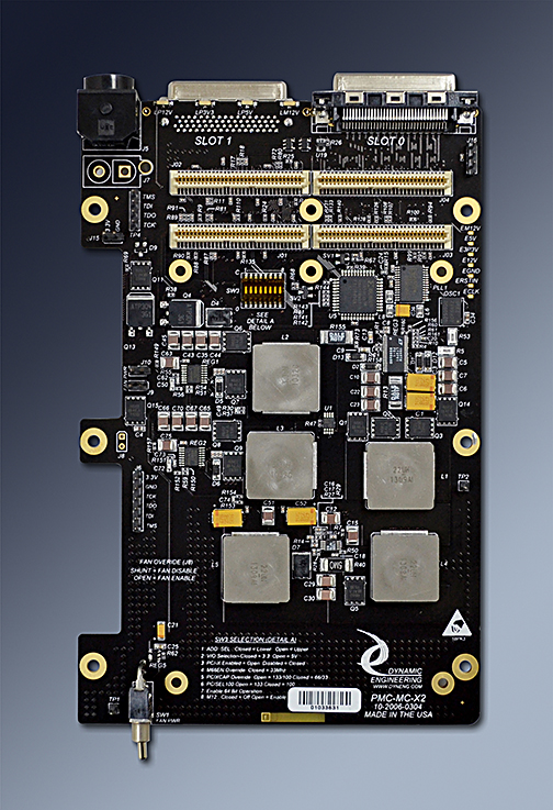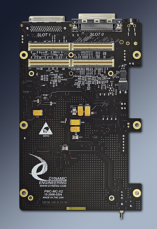


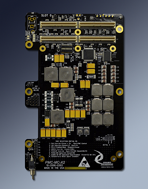
PMC-MC-X2-28
PMC Carrier with 2 Positions 28V version shown
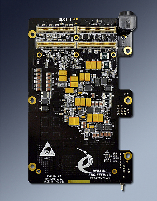


| Custom. Slightly larger than a PMC. Step files available. |
|
| |
|
| 2 PMC Slots provided. |
|
| |
|
| PCI bus can operate at 25,33,50,66,100,125 MHz. The PMC must be capable of the frequency to work properly. User switch plus PMC control to select frequency. 133 can be programmed at the clock generator and is an over-drive option. |
|
| Standard PCI byte lanes supported for byte, word, long, quad access dependent on installed PMC. |
|
| PMC register definitions as defined by installed hardware. No software set-up required by PMC-MC-X2. | |
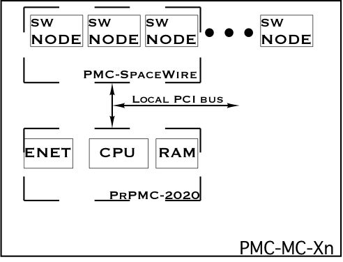
| INTA, B, C, D routed to PrPMC from PMC. Slot 0 is assumed to be populated with PrPMC. |
|
| |
|
| PCI signals are routed and terminated IAW the PCI specification. |
|
| |
|
| +5, +3.3, +12, -12V, and VIO supplied to PMC slots. |
|
| VIO is programmable by the user. |
|
| PMC-MC-X2 is a low power design with minimal heat dissipation of its own. Most PMC´s will require forced air cooling. Switched 5V [12V on RIO model] power is available for fans along with cut-outs on the side of the X2 to support closely mounted fans with little mechanical overhead. Industrial temperate parts used on both models. |
|
| Front Bezel IO supported on both models. RIO model has 2 VHDCI connectors with matched length impedance controlled interconnection to Pn4. |
|
| |
|
| +3V, +5V, +12V, -12V and "PMC Present". RIO model has rear edge mounted LED´s to be visible through rear of chassis. Voltage monitor circuits measure under and over voltage conditions. | |
| |
|
| optional JTAG header connected to PMC. JTAG pin definitions are in the silkscreen. |
| Direct connect non-bridge based design for optimum PCI performance. 25-125 PCI frequencies and 64/32 capable to work in your system. |
|
| |
|
| PMC-MC-X2 has the low cost of use. Make use of existing PMC designs in applications demanding high density without paying for the expense of a new design and layout. Quantity discounts are available. | |
| |
|
| 1 year warranty |
|
| |
|
| PMC-MC-X2 is easy to use. A plug and play interface to the PMC site. |
|
| |
|
| We work to keep the PMC-MC-X2 in stock. Send in your order for prompt delivery. Larger orders may have some lead time. |
|
| |
|
| PMC-MC-X2 is a custom board. Not much larger than a PMC Please see attached PDF for dimensions. |
|
| |
|
| PMC-MC-X2 is PMC compliant per the IEEE 1386 specification. All Dynamic Engineering PMC Modules are compatible with the PMC-MC-X2. |