Made in USA
The Embedded Solutions Experts
LiFePO4 Battery Cables
Order This Item
Coming SoonKey Features
- Interconnect LiFePO4 11.6 KWH batteries with controller
- Safe for more than 200A per cable set
- Custom Lengths
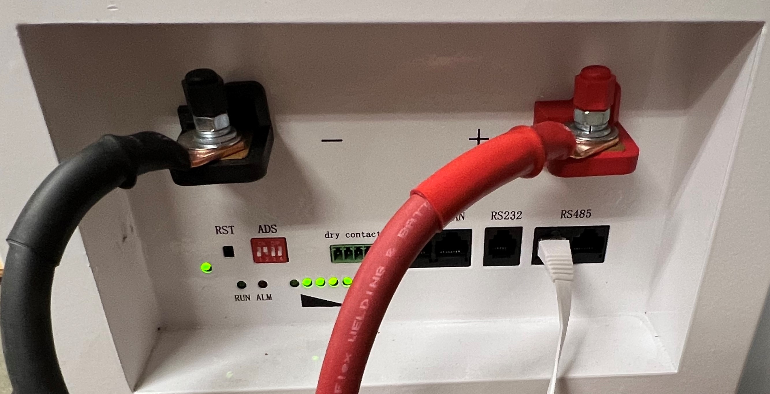
- Built with high quality lugs for battery connection - see photo
- Option for lugs or open on controller end
- Single and dual Battery models
- Use in parallel for larger banks,. Customize lengths for clean installation
- Suitable for many applications: Solar / PV system, emergency, off-grid, mobile, Data Server Farm
Cables are an important part of your installation. Undersized (for capacity) cables will create voltage drops between the controller and battery bank. The penalty is paid twice as it becomes less efficient to charge and discharge the batteries.
While this cable solution is designed with LiFePO4 11.6 KWH model in mind, they can be used with other batteries. Make sure the maximum current for the battery in use is the same or less than the LiFePO4 11.6 KWH model. The main concern is the maximum current for your configuration.
For installations with 1 battery we offer a model with terminals for one battery and one controller. For systems with 2 batteries and 2 controllers we offer a solution with a break out for the two batteries - the bus bar is built into the cable - and connections to the two controllers. For systems with 4, 6, 8 etc. batteries in parallel we offer the 2 unit model in parallel as well. This modular approach allows for wire sized for 2 batteries [more flexible] and different lengths for each pair if desired. A neater installation is possible using this approach.
The batteries are about 12" wide. The two batteries are connected in parallel and the joint between them roughly centered between them. The cable can be routed to the rear of the battery and over to the controller [or some other path as makes sense for your installation]. Since the batteries are 12" wide and there are two of them from center to center and some sort of air gap - say 1-2" we have about 25" extra length for the second set going out from the controller. Repeat for additional batteries. Be sure to meaure the entire length to have enough cable. For non- lug at the controller models you might want to order with a bit of extra length and cut to fit.
Battery Math
Stored Battery Power * efficiency = potential delivered power.
V*I*e = Watts Delivered = RMS voltage * current. Due to the battery being at a lower voltage than the RMS voltage the current delivered to the AC side is lower. For example : Battery at 52V, DC current 20A, e = .955 [from Sol-Ark 12KW] => 993.2W => 8.276A at 120V after conversion. The controller will likely display in terms of KW. Read the owners manual for the efficiency constant and how to interprete the display (before or after conversion).
Thermal Losses
In the example above the loss - power taken from the battery but not delivered to the load [generally becomes heat within the controller] = V*I*(1-e) => 52 * 20 * (1-.955) => 46.8W.
How much power does your house use? The answer is it depends. If you have converted to solar and gone electric with Refrigerators, Hot Water, Heat Pump, Oven, Dryer, well, etc. the load can be significant. There are two kinds of loads as well. When an appliance is first turned on there is an "in rush" current and after steady state a lower maintenance level. The amount of time and amount of current can vary a lot. An oven may use extra current coming up to temperature and then be much less once maintaining the temperature. A larger moter [well pump, heat pump etc.] may have a shorter duration higher intensity spike in requirements. When running on battery [ TOU, off grid, or black out] the current will have to come from the battery.
You can make a spread sheet and get the manufacturers ratings for everything and perform a worst case analysis to determine how much power you need to generate peak and for maintenance. Potentially you can program the devices to reduce the worst case requirement. For example depending on your well volume you might be able to run the well at a time unlikely to have the oven or dryer running. You may need to put in parallel controllers and batteries to support your load.
Parallel Batteries - Battery Banking
Each LiFePO4 11.6KWH battery [our model] can support 11.6 KWH of storage and 100A. Using the calculation above each battery can deliver 4966W to the load from each battery. If you are drawing this load you will have about 2 hours of run time. In our area TOU is 4pm to 9pm = 5 hours. Taking the effiency into the stored power value [11.6 * .955] and using 11.078 KWH we can divide by various wattage loads and see the expected run time. 11.078 / 5 => 2.21 KW or lower would be handled by a single battery. Remember the start-up case as your system may only average 2.2 KW but could easily exceed the 4.96 KW max current.
Many installations have 120/240 power circuits. The power delivered in the calculations above is based on 120V. If running at 240V the wattage is doubled meaning the run time is halved. We have 2 controllers in our set-up to have 240V power support with full rated current to each leg. We have batteries in parallel to support both loads. The batteries are connected in parallel to each other and to both controllers to allow load sharing between the batteries. In our system the max current from the batteries is programmable at the controller. Be careful to set this properly to be the amount of current each unit can draw. There is some measurement error within all controllers. It is recommended to leave some margin at the controller. Instead of programming to 100A use 85-90. The BMS will shut the battery down if too much is being requested by the controller. This will likely shut your sytem down. Most electronics and electrical equipment will last longer and be more reliable if you do not use the max values that can be programmed.
For off-grid systems the concept will be to go all night rather than just through the TOU or occasional black-out. The batteries can be paralleled up to 16 units. Each battery has a selector to allow a unique address on the chain allowing communication with each battery from a single connection. With 16 batteries in parallel one would have 100A *16 = 1600 A * 52V => 83 KW before efficiencies and 185.6 KWH. An impressive amount of stored power and maximum current. Assuming a slightly less expansive implementation: assume 8 hours of solar production meaning 16 hours from battery. Assuming the 5 KW for the entire time. We have 5 KW delivered 11.078 KWH per battery after efficiency reduction [for the controller - modify for your system]. 7.22 Batteries would be required. Obviously you would need to round up to 8 as the batteries come in integer quantities. In reality most homes do not consume that much power sustained. A few hours at the higher load when running the appliances but not the whole time. Our recommendation would be to size the wiring for the worst case and purchase 4 batteries to start with [for this scenario]. See what your run time really is and go from there. More batteries can be added to the initial group. Once you have the instantaneous current covered the run time is the main concern.
KW = Kilo Watt - this is a flow rate. Your Solar panels generate XX KW. If the power generated is accumulated [integrated] the KWH for the unit of time can be determined. For excample, in the winter the same array may not output the same percentage of capacity at any moment and for a shorter length of time per day leading to a x0, x1 or x2 for the whole day [against the rating of the array]. In summer the amount of available sunlight is greater and the intensity is also greater leading to a larger multiplier - x6+ on my personal system. The integrated generated power is the KWH for the day. Anywhere from close to Zero up to 80 KWH in a day all with the same 12KW rated system.
KWH = Kilo Watt Hour(s) - this is a unit of measure for the amount of power stored - the batteries capacity. 1 Kilo Watt for 1 hour.
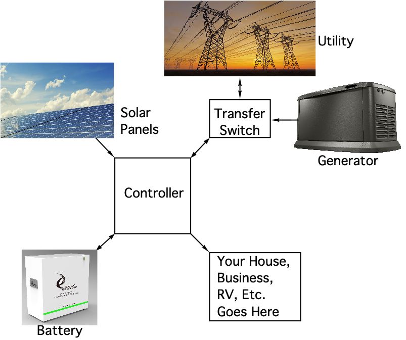
Controller Efficiency or conversion factor. The controller in your system uses Solar or Battery power and coverts to Load power. The load can be the utility if selling back or your house / business /vehicle etc. Power from the Solar Array PV (photovoltaic) panels is DC. Power from the batteries is also DC. Power delivered to the load is generally AC. In addition, power from the utility is used to charge the batteries - AC to DC in this case. The conversion from DC to AC or AC to DC is not perfect meaning there are losses associated with the conversion. Lower losses are better for your system life, for your power bill, and for the amount of useful power delivered from the battery.
Transfer Time is the time the controller takes to determine, and take action to switch sources when an event occurs - brown out, black out etc. Better controllers are faster. 4 mS and faster is a good target. Most appliances expect solid power. If the transfer time is very long the power in your installation will reduce in voltage [brown out] and you will see your lights flash and sometimes clocks and other items need to be reset. When the voltage is lower than expected the current used is increased. The increase in current can cause earlier failure of devices on the system, especially if the system is frequently correcting for Utility brown outs. With a faster unit the power switches quickly enough to act as a whole house UPS.
UPS Uninterruptable Power Supply. A device which monitors and frequently filters the local power. When the power input is disrupted, the device uses local storage to supply power to the device. Great protection when using a generator and transfer switch to fill the gap while the generator is coming on-line.
DC Direct Current. The voltage is at a level relative to ground. The voltage is relatively constant - for a battery the fully charged and fully utilized states will be different voltages. The rate of change is slow enough to be considered DC. The voltage decrease is relatively monotonic - not sinusoidal in nature. Power = Current * Voltage for DC applications.
AC Alternating Current. The voltage is sinusoidal. The peak voltage and the commonly measured voltage are not the same values. The handheld meter will display the RMS [root mean square] value for the waveform. Using RMS voltage allows a constant to be applied to sinusoidal waveform. If you integrate the power under the Sine wave to take into account the zero crossing and peak power you end up with the RMS equivalent.
Parallel when applied to controllers and batteries means connecting more than one together to create an increased supply. For example, use two controllers in parallel to double the power delivery, use two batteries in parallel to double the stored power. Sometimes referred to as a battery bank when operating in parallel. Parallel means + to + and - to - which keeps the voltage constant and increases the available storage and current. It is generally inadvisable to connect in series with Lithium batteries.
DOD Depth of Discharge - what percentage of the rated capacity can be utilized [discharged] per cycle and not affect the battery operation [number of cycles] Exceeding the DOD can damage the battery and reduce life-span
Duration The number of hours the battery can support the load. This figure is highly dependent on the load. See Battery Math section for some example calculations.
Battery Efficiency How much of the stored charge is used by the battery compared to how much can be delivered. This number depends on the test set-up as the BMS and other battery associated electronics will draw a fairly constant load while the time to discharge can vary greatly with the load applied. Shorter duration larger loads will appear to have a higher efficiency than smaller loads for a longer period. A better measure is the fraction of a KWH consumed by the battery. Usually this number is small compared to the efficiency loss in the DC/AC conversion - in terms of absolute power consumed.
V*I*e = Watts Delivered = RMS voltage * current. Due to the battery being at a lower voltage than the RMS voltage the current delivered to the AC side is lower. For example : Battery at 52V, DC current 20A, e = .955 [from Sol-Ark 12KW] => 993.2W => 8.276A at 120V after conversion. The controller will likely display in terms of KW. Read the owners manual for the efficiency constant and how to interprete the display (before or after conversion).
Thermal Losses
In the example above the loss - power taken from the battery but not delivered to the load [generally becomes heat within the controller] = V*I*(1-e) => 52 * 20 * (1-.955) => 46.8W.
How much power does your house use? The answer is it depends. If you have converted to solar and gone electric with Refrigerators, Hot Water, Heat Pump, Oven, Dryer, well, etc. the load can be significant. There are two kinds of loads as well. When an appliance is first turned on there is an "in rush" current and after steady state a lower maintenance level. The amount of time and amount of current can vary a lot. An oven may use extra current coming up to temperature and then be much less once maintaining the temperature. A larger moter [well pump, heat pump etc.] may have a shorter duration higher intensity spike in requirements. When running on battery [ TOU, off grid, or black out] the current will have to come from the battery.
You can make a spread sheet and get the manufacturers ratings for everything and perform a worst case analysis to determine how much power you need to generate peak and for maintenance. Potentially you can program the devices to reduce the worst case requirement. For example depending on your well volume you might be able to run the well at a time unlikely to have the oven or dryer running. You may need to put in parallel controllers and batteries to support your load.
Parallel Batteries - Battery Banking
Each LiFePO4 11.6KWH battery [our model] can support 11.6 KWH of storage and 100A. Using the calculation above each battery can deliver 4966W to the load from each battery. If you are drawing this load you will have about 2 hours of run time. In our area TOU is 4pm to 9pm = 5 hours. Taking the effiency into the stored power value [11.6 * .955] and using 11.078 KWH we can divide by various wattage loads and see the expected run time. 11.078 / 5 => 2.21 KW or lower would be handled by a single battery. Remember the start-up case as your system may only average 2.2 KW but could easily exceed the 4.96 KW max current.
Many installations have 120/240 power circuits. The power delivered in the calculations above is based on 120V. If running at 240V the wattage is doubled meaning the run time is halved. We have 2 controllers in our set-up to have 240V power support with full rated current to each leg. We have batteries in parallel to support both loads. The batteries are connected in parallel to each other and to both controllers to allow load sharing between the batteries. In our system the max current from the batteries is programmable at the controller. Be careful to set this properly to be the amount of current each unit can draw. There is some measurement error within all controllers. It is recommended to leave some margin at the controller. Instead of programming to 100A use 85-90. The BMS will shut the battery down if too much is being requested by the controller. This will likely shut your sytem down. Most electronics and electrical equipment will last longer and be more reliable if you do not use the max values that can be programmed.
For off-grid systems the concept will be to go all night rather than just through the TOU or occasional black-out. The batteries can be paralleled up to 16 units. Each battery has a selector to allow a unique address on the chain allowing communication with each battery from a single connection. With 16 batteries in parallel one would have 100A *16 = 1600 A * 52V => 83 KW before efficiencies and 185.6 KWH. An impressive amount of stored power and maximum current. Assuming a slightly less expansive implementation: assume 8 hours of solar production meaning 16 hours from battery. Assuming the 5 KW for the entire time. We have 5 KW delivered 11.078 KWH per battery after efficiency reduction [for the controller - modify for your system]. 7.22 Batteries would be required. Obviously you would need to round up to 8 as the batteries come in integer quantities. In reality most homes do not consume that much power sustained. A few hours at the higher load when running the appliances but not the whole time. Our recommendation would be to size the wiring for the worst case and purchase 4 batteries to start with [for this scenario]. See what your run time really is and go from there. More batteries can be added to the initial group. Once you have the instantaneous current covered the run time is the main concern.
Definitions and Clarifications:
Part Number: LiFePO4 XXX KWH
Ordering Options
- LiFePO4 - 60-2022-1160 = PN. LiFePO4 Lithium Iron Phosphate rechargable battery. 100A, 11.6 KWH, 6000+ discharge / recharge cycles. One Serial cable set per order. Lead time is stock to 80 days. Batteries are billed 50% down, 50% when ready to ship. Batteries can be shipped or picked up from our facility.
Manuals
Manual for LiFePO4 11.6KWH in PDF format.