Made in USA
The Embedded Solutions Experts
PCIBPMC
PCI adapter for PMC

PCIBPMC Description
- Industrial Temperature
- PCI 32 bit 25-66 MHz Interface
- PMC position with PCI interface supporting PCI [32/33 <=> 32/66]
- Plug and Play operation [transparent bridge]
- 1/2 Length PCI Card
- "Zero Slot Fan"™ Compatible
- Bezel I/O and Jn4 I/O for PMC
- 1 Year Warranty Standard. Extended Warranty Available.
- ROHS and Standard Processing Available
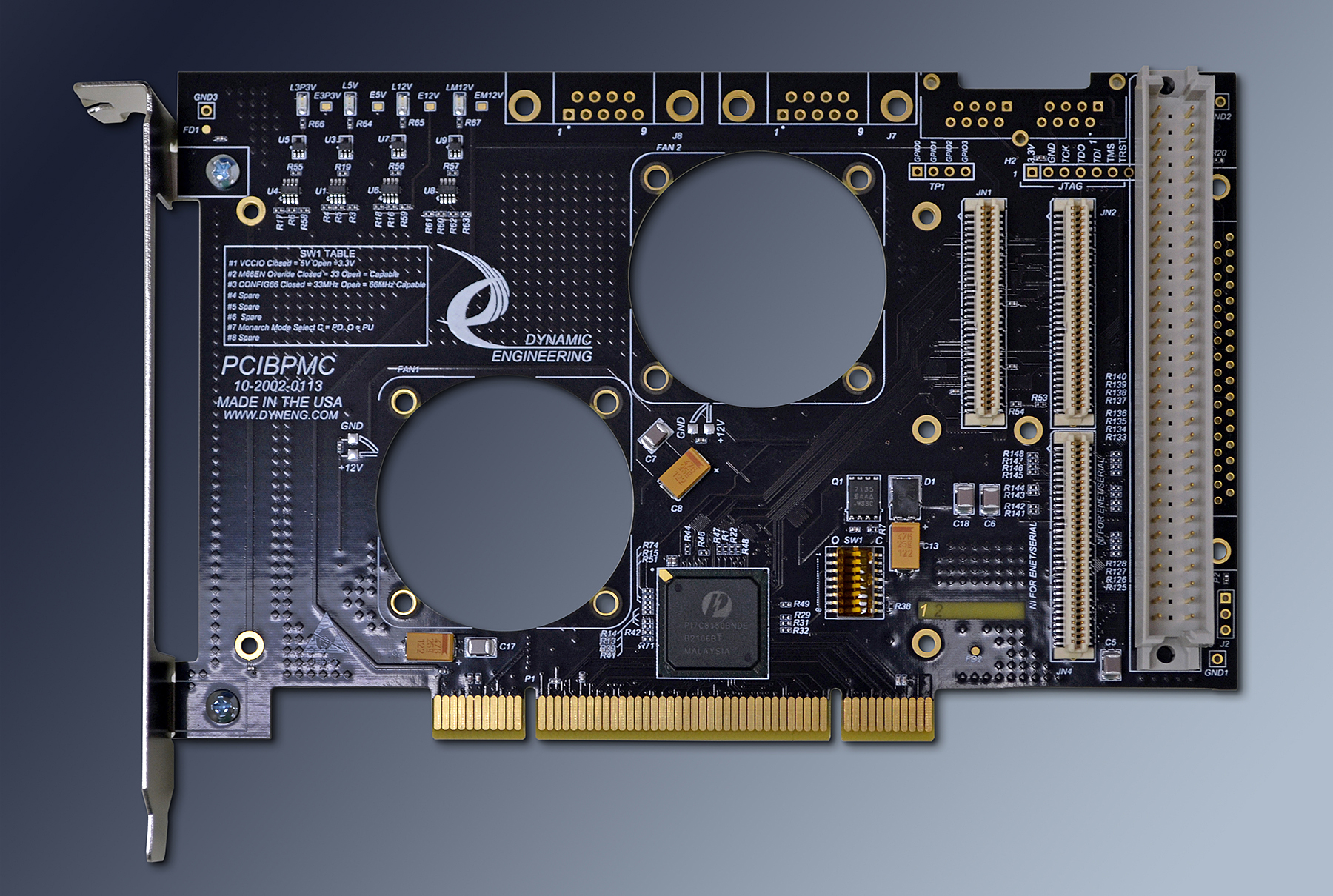
Dynamic Engineering has done the hard part for you with impedance controlled, PCI compliant routing, matched length IO, extended temperature bridge, high speed differentially routed Ethernet, local DC/DC power supply and more. Sometimes beauty is more than skin deep. With PCIBPMC ( PCI Bridge PMC ) adapter / carrier converter card all you have to do is install your PMC onto the adapter, and then plug into the PCI slot. PCIBPMC is a universal voltage 1/2 length PCI card. Suitable for 32 bit bus operation. The bridge operates in transparent mode to provide plug and play operation. The PMC slot can be programed with user jumpers to use 3.3 or 5V for VIO.
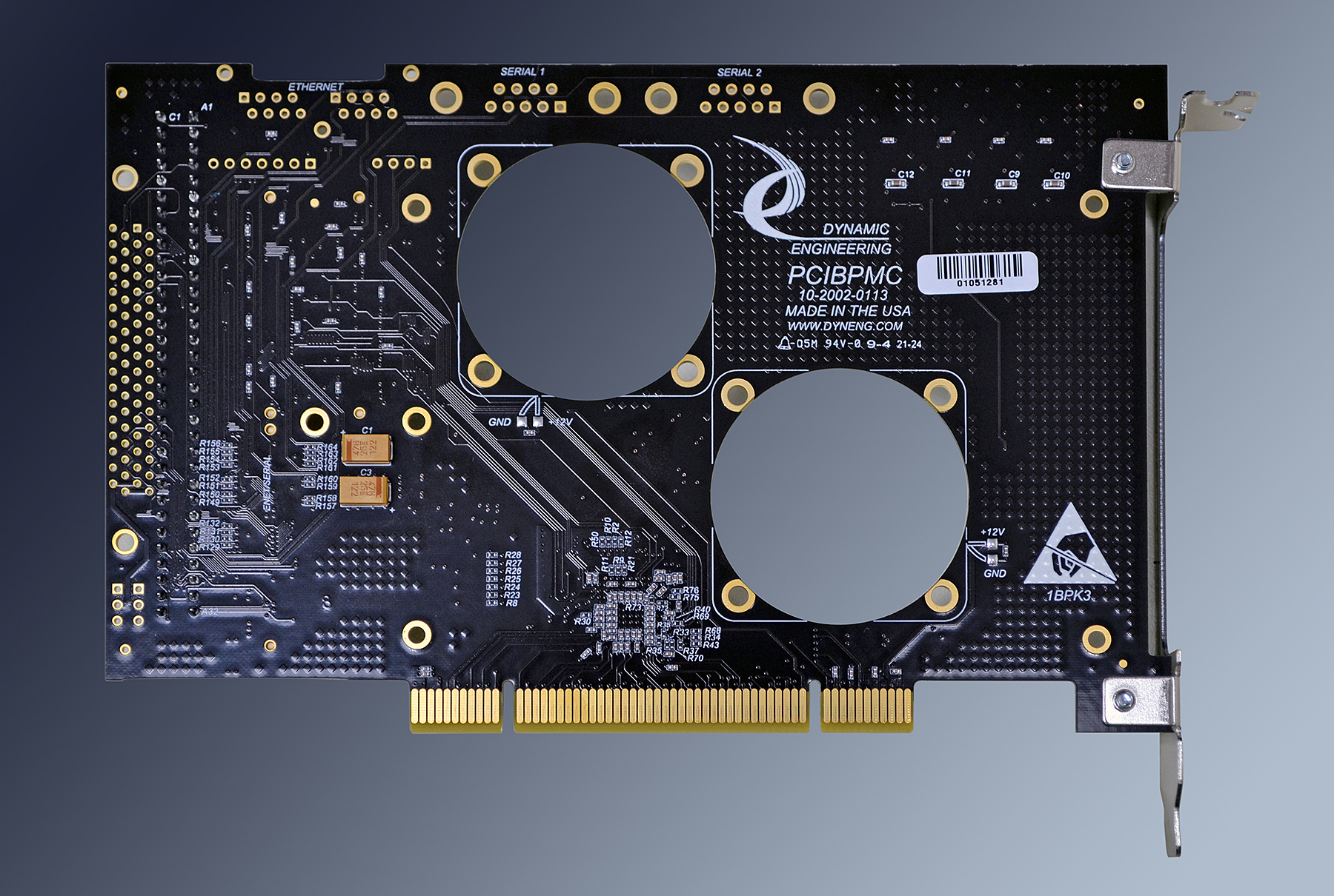
The PMC user IO connector Pn4 is routed to one of two connectors for access (DIN IDC or SCSI II). The signals corresponding to the PrPMC standard Ethernet and Serial lines can optionally be connected to the Ethernet and Serial port connectors at the top edge of the board. The signals are isolated with resistors to keep the routing short. The PMC front panel connector is mounted though the PCI mounting bracket.
For superior performance PCIBPMC has cooling cutouts for increased airflow to the PMC. If your application requires a fan you can order the PCIBPMC-FANx to have a fan(s) mounted to your PCIBPMC. The forward position is #1.
The PCI bus is interconnected to the PMC via a 32 bit 66 MHz capable bridge. The bridge allows the PCI bus to operate with different parameters than the PMC card - for example the PCI bus can operate at 66 MHz and the PMC with 33 mhz. The buffering within the bridge will take care of the rate matching. The local side can also operate at 66 if the PMC supports it. PCIBPMC can control the M66EN signal via a dipswitch setting or the PMC can control the M66EN setting directly.
The voltage definitions are also buffered between the PCI and PMC buses. The PCI VIO automatically defines the reference levels for the primary side of the bridge. A shunt is used to control a MOSFET to select which voltage reference is used on the secondary side. A 5V PMC card can be used with a 3.3V PCI bus and vice-versa. The voltages can also be the same.
The bridge insures that multiple PCIBPMC cards can be installed onto the same PCI bus stub.
The PCI power rails [+12, -12, 3.3V, 5V and ground] are routed to the PMC using planes with more current capacity than spec for PCI/PMC. Each of the rails is bipassed on PCIBPMC with both bulk and high speed decoupling capacitors. The decoupling capacitors are located at the connector pins, bridge pins etc.
The individual pins on the JN4 (PN4) connector are accessible via SCSI or DIN. The routing is matched length from Pn4 to the connector pins. With the SCSI connector option we recommend using with our SCSI cable and the HDEterm68 breakout block for ease of debugging. To mate with the VME DIN connector; DINterm64 is a 64 position terminal strip compatible with the PCIBPMC and the DIN Ribbon Cable 64 is a 64 position ribbon cable that can be used to interconnect the carrier with the terminal strip.
The PMC JTAG connections are routed to an optional header strip suitable for use programming your FPGA. 3.3V, GND, TCK, TMS, TDI, TDO, TRST. Please let us know if you want the header installed by adding -JTAG to your ordered PN.
The power rails are measureed and LEDs illuminated if within tolerance. If the LEDs are out check your system power supply.
PCIBPMCX1 was the twin to this design with PCI-X bridge and differential routing to the rear connector. Contact us if you want a modified version of this design with matching rear IO [to the X1 version].
PCIBPMC Features
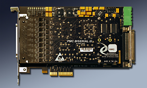
PCIeBPMCX1 shown loaded with a Dynamic Engineering PMC BiSerial Module PCIBPMC uses the same mounting locations and bezel.
Size
1/2 size PCI card with
PMC compatible slots
1 PMC position provided. DMA capable
Clocks
PCI primary and secondary buses can operate at PCI(66, 33) MHz. User switch or automatic selection on secondary side. Set by system on primary side.
PMC VIO
Selectable between 5V and 3.3V
Software Interface
Industry Standard Bridge register definitions. The bridge does not require any user set-up. PMC register definitions as defined by installed hardware.
Power
Power Planes interconnect PCI and PMC with +5(8A), +12, -12V(1A), +3.3V(12A) available. Current supplied is dependent on system power supply and backplane capability. It is recommended to use the FAN option for high power requirement PMCs.
Thermal
PCIBPMC has cut-outs to support increased airflow over the PMC´s component side. Optional fan(s) with two mounting positions per PMC position are available and recommended for many applications. Industrial Temperature components.
Interrupts
INTA, INTB, INTC, INTD routed to the PCI connector. Most PMCs use one Interrupt level [INTA].
IO Interface
PMC Bezel IO supported at PCI bracket. Jn4 "user IO" Differential, Impedance controlled, matched length traces from Jn4 to SCSI connector.
Specification
PMC, PCI, and PCIe specification compliant
LED´s
+3V, +5V, +12V, -12V[with voltage monitoring] and Busmode 1 [present]
JTAG
PMC JTAG connections are tied to a labeled header. Add -JTAG to part number for this option to be installed.
Statement of Volatility
Reliability
1.27 Million hours per Bellcore SR-332 GB 25C [conservative value from previous bridge implementation]
Weight
~4.7 oz typical, standard configuration. Add .65 oz. for two fans
Export Classification
EAR99, HTS:8537.10.9050
PCIBPMC Benefits
Speed
PCIBPMC offers PCI speeds at the PMC position. Fully optimized bridge with buffering to support DMA streaming and other stressing activities.
Price
Make use of existing PMC designs in PCI applications without paying for the expense of a new design and layout. Quantity discounts are available.
Ease of Use
PCIBPMC is easy to use. A plug and play interface to the PMC site. The Bridge can be configured with the user switch on board. PCIBPMC uses a Transparent Bridge. In most cases the switches can be left with the factory settings. The manual contains clear directions for switch options.
Availability
PCIBPMC is a low stock board as PCI is giving way to PCIe. We keep the default models in stock. We pre-build with the common devices installed, and then cllientize to your specific configuration. This method allows faster delivery on our more popular products while retaining the ability to have multiple client options. On-site manufacturing allows for larger orders to be quickly built.
Size
PCIBPMC is a 1/2 size PCI board which conforms to the PCI mechanical and electrical specifications. Eliminate mechanical interference issues. PCIBPMC can be used in all 1/2 and full length PCI compliant slots.
PMC Compatibility
PCIBPMC is PMC compliant per the PMC specification [compliant per the IEEE 1386]. All Dynamic Engineering PMC Modules are compatible with the PCIBPMC. All other PMC Modules which are compliant with the PMC specification are compatible with PCIBPMC
PCI Compatibility
PCIBPMC is PCI compliant. PCIBPMC can be expected to work in any PCI compliant backplane. The bridge is Revision 2.2 compliant.
Part Number: PCIBPMC
Ordering Options
- PCIBPMC Standard board - Standard Build, DIN connector, standard processing.
Order combinations of the options by simply adding the extension(s) to your order request. - -FAN( ) Need additional cooling? order the PCIBPMC-FAN() for a pre-installed 12V 5.2CFM fan(s) to maximize cooling and functionality of your card. The fan has been tested with high wattage prPMC devices.
Fan position 1 is closest to the PCI bezel. Valid Fan options include:
(1 or 1Rz) position 1 only low profile or rear mount.
(2 or 2Rz) position 2 only low profile or rear mount.
(1R) 8 CFM fan position 1 available as R mount only .
(2R) 8 CFM fan position 2 available as R mount only .
Any combination with at most 1 fan per position defined. - -ROHS Use ROHS processing. Standard processing is "leaded"
- -CC Option to add Conformal Coating
- -NC Order to receive a PCIBPMC with no SCSI or DIN connector installed.
- -SCSI Order to receive a PCIBPMC with SCSI instead of DIN connector installed.
- -VIO3 The VIO3 option removes the FET for the secondary VIO to force it to be 3.3V only � for no mistakes about voltage selection
- -JTAG Order to receive a PCIeBPMCX1 with the JTAG header installed
PCIBPMC Drivers
Software Support for PCIBPMC is not needed. PCIBPMC has a transparent bridge, the drivers and application SW associated with the PMC will not need changing to use this carrier.
Please see the PMC Driver manual for the specifics of operating the installed device.
Please see the PMC Driver manual for the specifics of operating the installed device.