Made in USA
The Embedded Solutions Experts

Embedded Design
Capabilities For Making Embedded Solutions

Interfaces, Standards, Formats
Dynamic Engineering provides off-the-shelf and customized designs. IP-BiSerial was the first configurable platform. Specialized interfaces were added and the design updated to support PMC, PCIe, PCI-104, conduction cooled models, special form factors, other IO types etc. Module carriers were added to support other host interfaces. In addition to expanding the BiSerial family, other interface types have been added: TTL, ECL, PECL, NECL, A/D, D/A, HOTLink, Wizard Link, etc.The list below shows some of the interface types implemented by Dynamic Engineering. Many additional types can be found on the dynamic data page for each product. The list and descriptions are meant to provide the basics of the interface. Follow the links to a representative interface for more information. Not all options are listed. Write or call if with your requirements, we may already have the interface or can port and update to provide it for you.
User Design
With company proprietary or classified design it can be hard to work with a third party to develop the interface. User Design implementations have features to support client design work. Special features: downloadable files into the FPGA for development, Ease of programming the FPGA configuration, flexible IO [Inputs, Outputs, Termination, type etc], reference clock support [PLL inputs with programmable references], over designed power supplies etc. to handle anything the user can implement. A good reference design to support client implementation. Flexible SW interface to support client modification of the design.
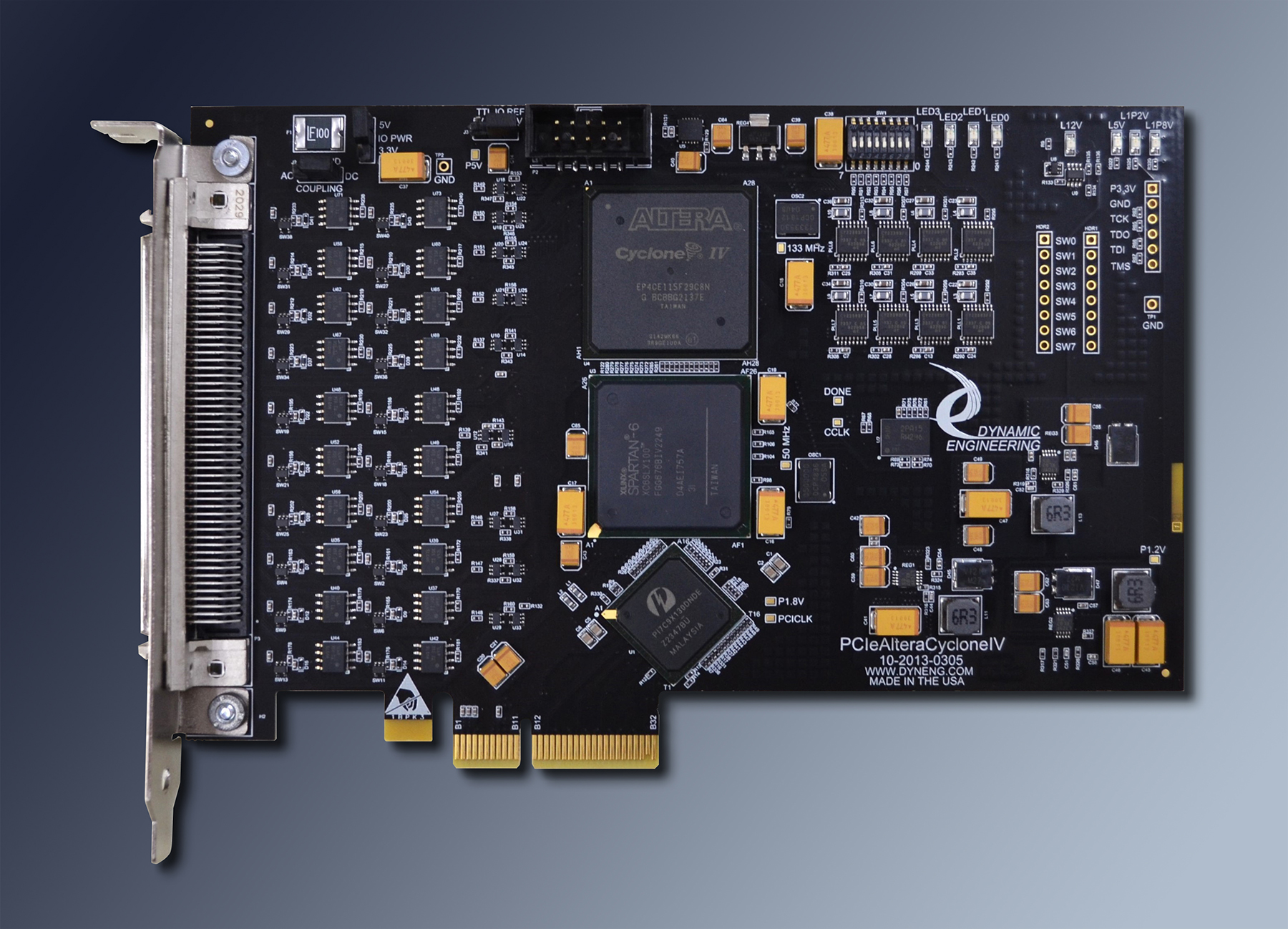
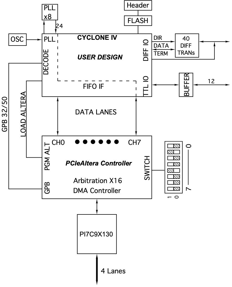
PCIe-AlteraCycloneIV PCIe design with User configurable Cyclone IV, plus 40 differential [RS485 / LVDS] IO with programmable direction and termination, 12 single ended [LVTTL] IO, multiple PLLs, PCIe- FIFO interface plus PCIe decoded parallel bus, 16 DMA ports built in.
PCIe-Spartan-VI PCIe design with User configurable Spartan VI 100, plus 40 differential [RS485 / LVDS] IO with programmable direction and termination, 12 single ended [LVTTL] IO, multiple PLLs, PCIe- FIFO interface plus PCIe decoded parallel bus, 16 DMA ports built in.
IP-BiSerial-VI-USER IndustryPack with Spartan 6 25 FPGA, PLL, programmable direction and termination for each of 24 differential pairs [RS485 / LVDS]
Manchester
Manchester Endoding incorporates the clock into the data by requiring a change of state within each bit period. Called Bi-phase. Changes happen mid bit period. Depending on the particular encoding consecutive ones or zeros look like As and 5s due to the encoding requirement. This feature helps with line balancing allowing longer transmission lengths [similar to 8B10B and other encodings] by not allowing the line to become static. Can be single ended, differential, Bi-Phase etc.
PMC-BiSerial-VI PMC design with LVDS and or RS-485 IO, PLL, FPGA. Multiple Manchester based designs.
IP-BiSerial-VI IndustryPack design with LVDS and or RS-485 IO, PLL, FPGA. Multiple Manchester based designs.
PMC-BiSerial-VI PMC design with LVDS and or RS-485 IO, PLL, FPGA. Multiple Manchester based designs.
IP-BiSerial-VI IndustryPack design with LVDS and or RS-485 IO, PLL, FPGA. Multiple Manchester based designs.
NRZ, NRZL
Non-Return-to-Zero & Non-Return-to-Zero-Level - Both are basically the same with differential IO and frequently with a clock reference. Encoded directly '1' = 1,0 '0' = 0,1 on the differential pair. Sometimes combined with synchronization patterns, encoding, and known clock rates to eliminate the separate clock. See Manchester etc.
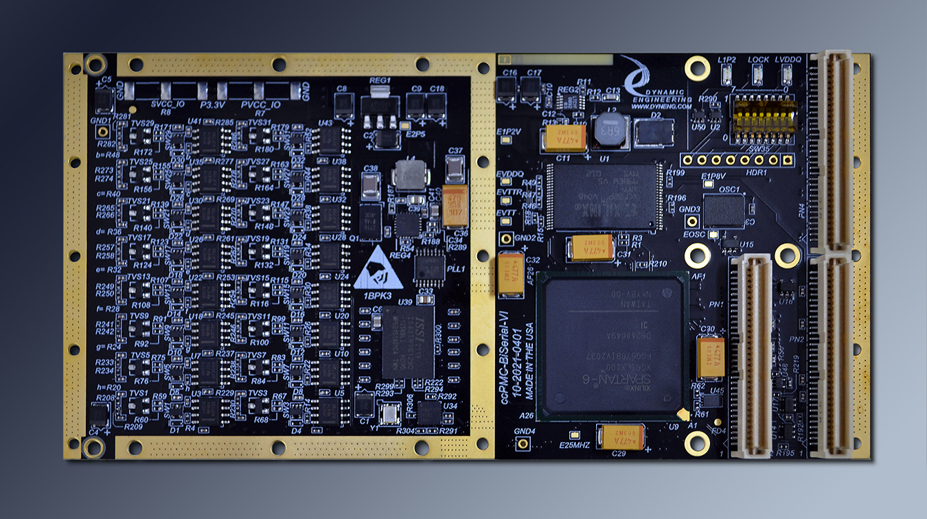
ccPMC-BiSerial-VI-ORN1 Programmable Bit count, MSB/LSB first, Clock sense, Data Sense for the NRZ/NRZL ports plus 2 SDLC ports.
ccPMC-BiSerial-VI-ORN1 Programmable Bit count, MSB/LSB first, Clock sense, Data Sense for the NRZ/NRZL ports plus 2 SDLC ports.
SpaceWire
ECSS-E-ST-50-12C specification - LVDS signaling, SIN, DIN cross connected with SOUT, DOUT. 1-200 MHz typical. 10 MHz used for initial link connection. Used mainly with spacecraft and related hardware.
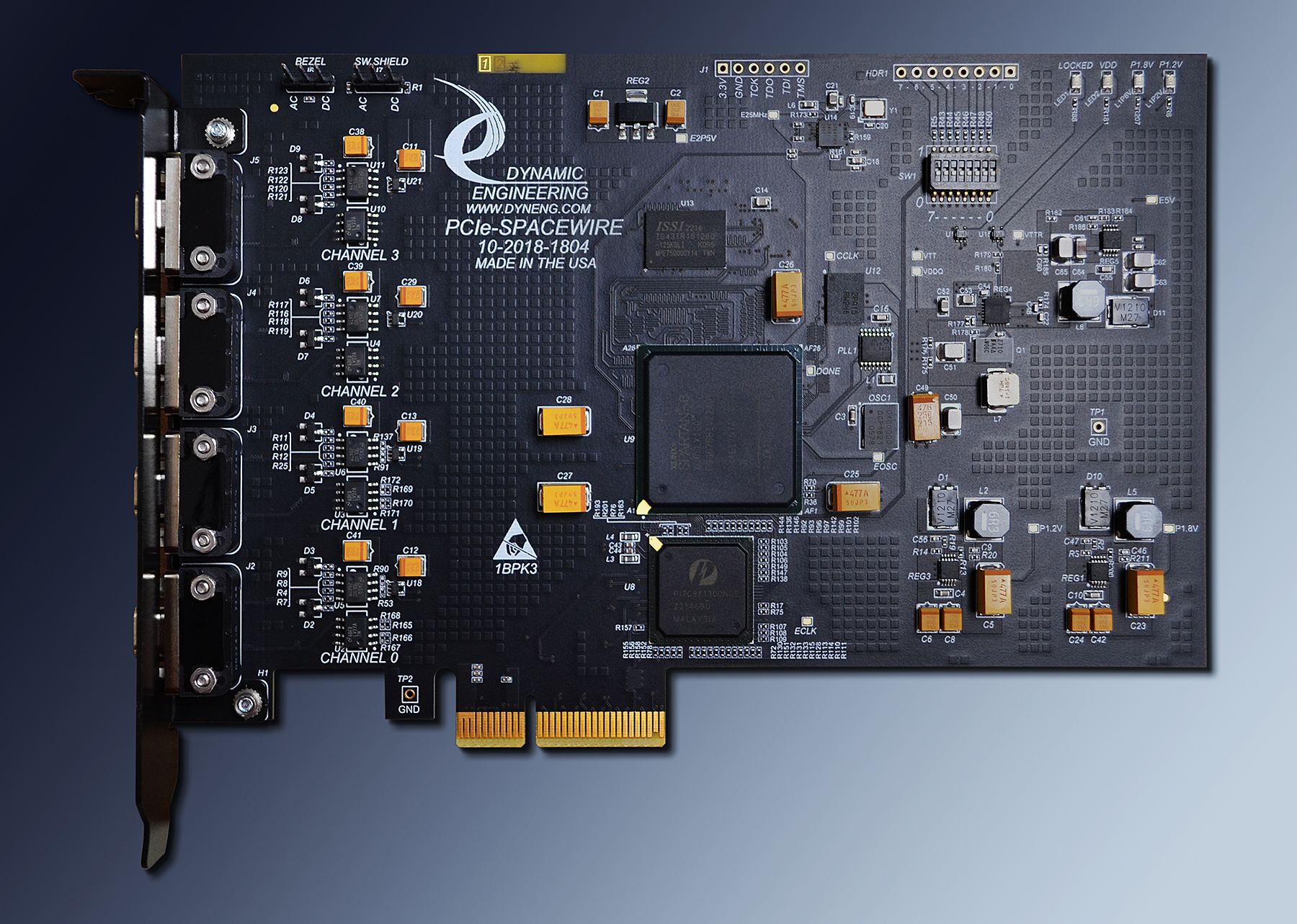
PCIe-SpaceWire 1/2 length PCIe implementation with 4 channels at bezel. 32 MBytes of storage per Rx and Tx Port.
PCI-SpaceWire 1/2 length PCI design with 4 channels at bezel
PMC-SpaceWire Standard PMC with 3 channels at bezel, or 4 at Pn4
PC104p-SpaceWire standard PCI-104 device with 4 channels
Each design features independent DMA, time code, PLL - user frequencies, Industrial temperature. Windows, Linux, VxWorks
SpaceWire Cables, Break Out, Monitor, RMAP functions also available.
ARINC 429
Aeronautical Radio Inc standard 429 is the replacement for CSDB(Commercial Standard Digital Bus). 429 is manchester encoded and selectable between 12.5 KHz and 100 KHz. 2 wire system with enough voltage swing to provide good noise immunity. 429 defines the electrical interconnection and format of messages on the line allowing for interoperability of navigation and other equipment mainly on aircraft.
IP-429 IndustryPack with 1-4 TX and 2-8 Rx ports implemented
PC/104p-Baseboard Custom design with PC104 stack support, 429, OptoISO Inputs and outputs, D/A and A/D, plus differential UART
ccXMC-RAR15XC Custom conduction cooled XMC with 1553 [4 dual redundant ports], 429 [8 TX, 10 RX] plus Aircraft Discrete interface
MIL-STD-1553
Manchester II Bi-phase L bit encoding. 2 wire interface with redundant port and trapezoidal waveform. 1st half of bit period is the value. Finding 2 high 1/2 periods in a row is a 0,1. Faster than 429 and with potential for larger message communication. Used in many rugged systems. Bus Controller, Remote Terminal, and Bus Monitor functions defined.
IP-1553 IndustryPack with 1 or 2 Dual Redundant 1553 interfaces. Selectable direct coupled or transformer coupled operation.
ccXMC-RAR15XC Custom conduction cooled XMC with 1553 [4 dual redundant ports], 429 [8 TX, 10 RX] plus Aircraft Discrete interface
IP-1553 IndustryPack with 1 or 2 Dual Redundant 1553 interfaces. Selectable direct coupled or transformer coupled operation.
ccXMC-RAR15XC Custom conduction cooled XMC with 1553 [4 dual redundant ports], 429 [8 TX, 10 RX] plus Aircraft Discrete interface
CAN
Controller Area Network - Specialized interface based on NRZ encoding with bit stuffing. Multi-drop with termination [120 ohms] at end points. STP or UTP wiring. 10 Kbits to 1 Mbit per sec. DB9 is standard connector.
IP-CAN IndustryPack with 1 or 2 CAN interfaces. Option for Direct or Isolated interface. Programmable termination.
IP-CAN IndustryPack with 1 or 2 CAN interfaces. Option for Direct or Isolated interface. Programmable termination.
Parallel-Differential
GPIO (General Purpose Input Output) is usually register based with software controlling the state of each line in the port - transmit or receive, data on line when transmitting, termination. Many designs have Change of State interrupt capabilities, some have programmable frequencies for sampling, updates.
IP-Parallel-IO IndustryPack with upto 24 RS-485 or LVDS differential pairs. Can be ordered with mixture of TTL and Differential IO
IP-BiSerial-VI-GPIO IndustryPack GPIO interface, COS, PLL
PMC-Parallel-485 PMC with 32 programmable IO. Can be ordered with LVDS IO
PMC-BiSerial-VI PMC with 32 transceivers each with independent direction and termination control. Multiple designs - many use spare IO for parallel ports. -GPIO design can be ported to this one from ccPMC-BiSerial-VI model.
Parallel-Single Ended
GPIO (General Purpose Input Output) is usually register based with software controlling the state of each line in the port - TTL or similar levels, input or output, value to transmit. COS and other features may be present.
IP-Parallel-IO IndustryPack with up to 48 TTL IO . Can be ordered with mixture of TTL and Differential IO
PMC-Parallel-TTL PMC with 64 TTL IO . Open drain, programmable 3.3V or 5V pull-up reference. Temperature sensor
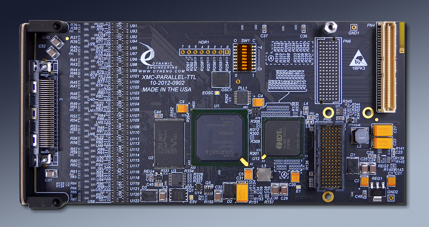
XMC-Parallel-TTL XMC with 64 TTL IO . Open drain, programmable 3.3V or 5V pull-up reference. Temperature sensor. Lane LEDs. VPWR status.
IP-Parallel-IO IndustryPack with up to 48 TTL IO . Can be ordered with mixture of TTL and Differential IO
PMC-Parallel-TTL PMC with 64 TTL IO . Open drain, programmable 3.3V or 5V pull-up reference. Temperature sensor
XMC-Parallel-TTL XMC with 64 TTL IO . Open drain, programmable 3.3V or 5V pull-up reference. Temperature sensor. Lane LEDs. VPWR status.
HOTLink
Cypress Semiconductor [now part of Infineon] invented HOTLink utilizing PECL and 8B10B encoding / decoding to create a point to point link. LVDS, ECL and other IO types have been adapted to HOTLink. Serial rates up to 400 Mbits per sec with the first generation of interface devices. K char used to create start of frame, end of frame, NULL etc.
ccPMC-HOTLink Conduction Cooled PMC with 6 HOTLink ports. Options for transformer coupling. 12 RS485 IO. Independent DMA for each Tx and Rx.
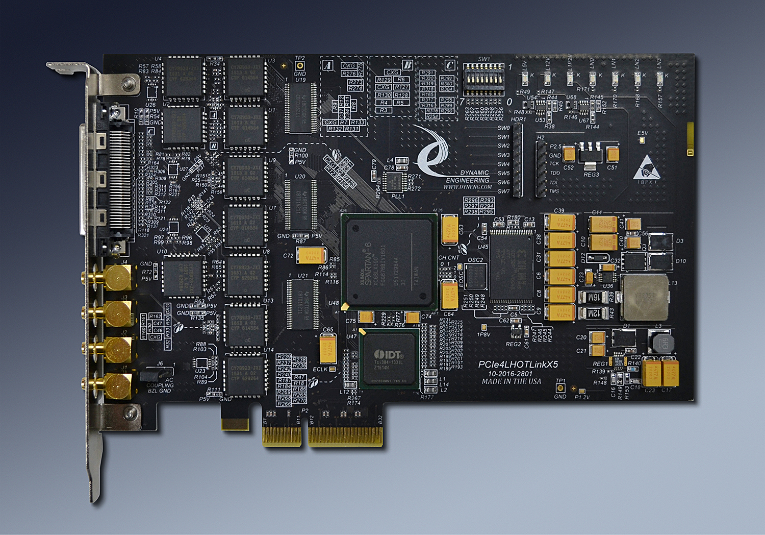
PCIe4lHOTLinkx5 PCIe design with 5 HOTLink Ports. 0-3 on VHDCI connector. Port 4 on SMB. Fiber interface signals on VHDCI connector. Independent DMA for each Tx and Rx. LVDS IO option.
PCIe4lHOTLinkx6 PCIe design with 6 HOTLink Ports. 0-3 on RJ45 connector - half duplex operation. Port 4, 5 on 2nd RJ45 with full duplex operation. Independent DMA for each Tx and Rx. LVDS IO option.
ccPMC-HOTLink Conduction Cooled PMC with 6 HOTLink ports. Options for transformer coupling. 12 RS485 IO. Independent DMA for each Tx and Rx.
PCIe4lHOTLinkx5 PCIe design with 5 HOTLink Ports. 0-3 on VHDCI connector. Port 4 on SMB. Fiber interface signals on VHDCI connector. Independent DMA for each Tx and Rx. LVDS IO option.
PCIe4lHOTLinkx6 PCIe design with 6 HOTLink Ports. 0-3 on RJ45 connector - half duplex operation. Port 4, 5 on 2nd RJ45 with full duplex operation. Independent DMA for each Tx and Rx. LVDS IO option.
UART
Universal Asynchronous Receiver Transmitter. When idle the transmitter is in the marking state = '1' which can be various levels depending on the medium involved [RS-232, RS485, LVDS etc.] Characters begin with the start bit which is a '0 ' immediately following the marking state. Lsb to Msb data with 8 bits most common but some interfaces use fewer bits. Optional parity is next and can be odd or even. At least 1 stop bit [same state as the marking bit] follows the optional parity. "8N1" is a typical description showing 8 bits no parity and 1 stop bit. The UART was initially used with low speed operation. Since no reference clock the receive side samples the received signals with [typical 16x] clock to decode the received characters. The 16x clock puts an upper limit on throughput since a 10 MHz bit period rate would mean a 160 MHz sample rate. Most common rates are sub 1 MHz. RS-232 can be used up to the 400 KHz rate + or - depending on cable quality and length. Above this frequency most designs use differential IO of some sort with RS-485/RS-422 the most popular.
IP-QuadUART IndustryPack with 4 16550 compatible UARTs, programmable RS-232 or RS485 operation per port.
IP-QuadUART-485 IndustryPack with 16C854 - 4 16550 compatible UARTs, RS485 interface with MODEM control signals
PMC-OctalUART-232 PMC with 8 16550 compatible UARTs, RS232 interface with RTS/CTS and DSR/DCD control signals
PMC-BiSerial-VI-UART PMC with 8 customized UARTs. RS-485 or LVDS operation. Packet mode, 32 bit packed data, byte packed data and more. 16 DMA engines. High speed operation.
Miller
Serial data encoding/decoding method. Can be used with any medium. Encoded information is in the spacing between transitions. Also called DMM or Delay Modulation. 1.0, 1.5, and 2.0 bit periods are measured with 10x clock to decode or encode the data. More efficient than Manchester encoding.
IP-BiSerial-VI-MLR IndustryPack design with transmit and receive ports with Miller encoding. Currently see description on IP-BiSerial page - this design is being ported forward.
IP-BiSerial-VI-MLR IndustryPack design with transmit and receive ports with Miller encoding. Currently see description on IP-BiSerial page - this design is being ported forward.
Isolation
Sometimes the electrical separation between the external and internal circuit needs to be enhanced to meet an isolation requirement. The isolation can be provided by various means including optical, isolated power supplies, galvanic, and sometimes resistive. Alternatively some designs have features to support withstanding ESD or other external events [lightning etc.].
IP-Relay16 provides 16 Form C relays for high and low side switching with 1.5A and 220/250 V contact capabilities plus the isolation provided by the relay.
IP-OptoISO-16 provides 16 Optically isolated FET switches with 60V and 1.5A. 4000V RMS isolation.
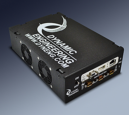
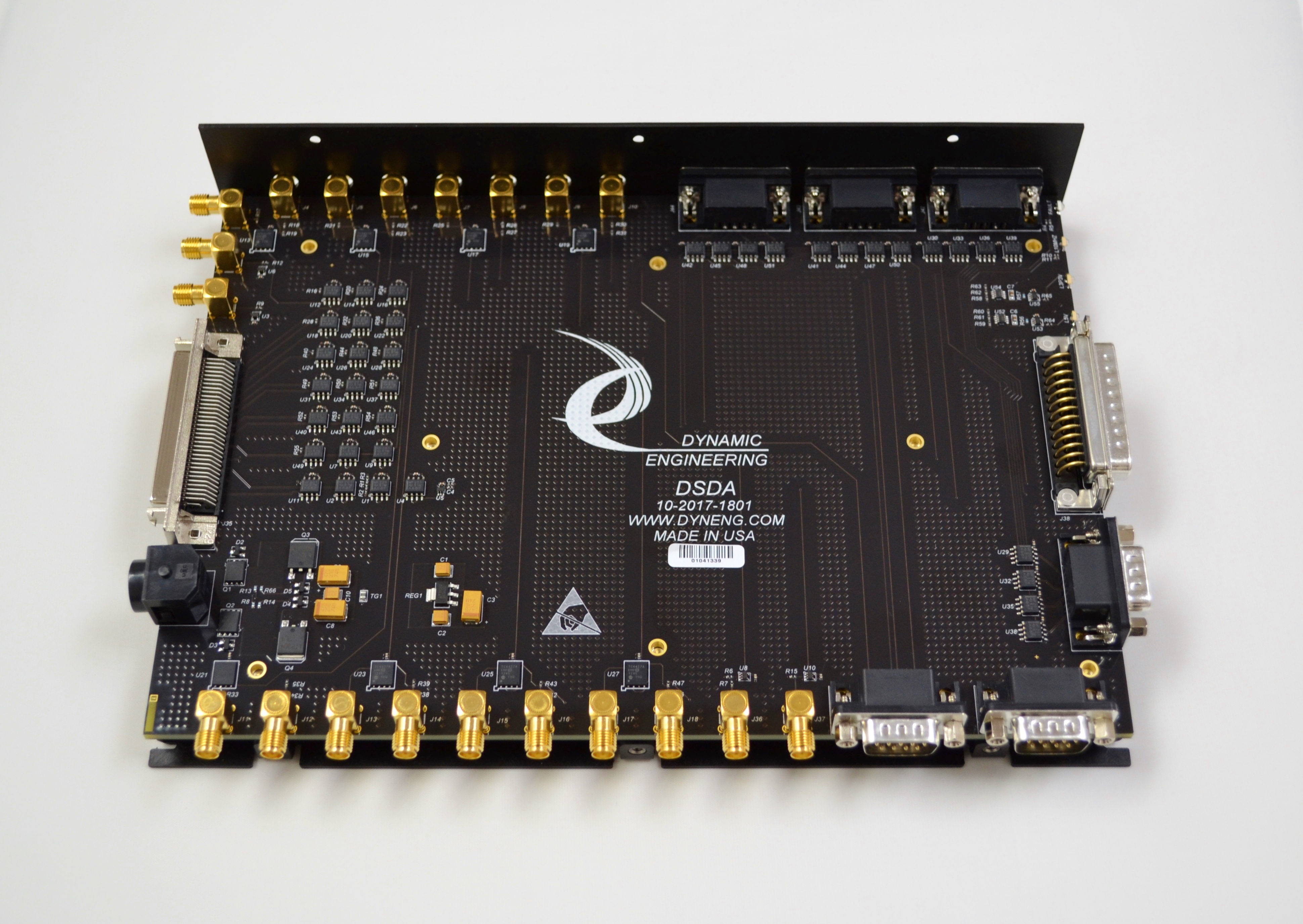
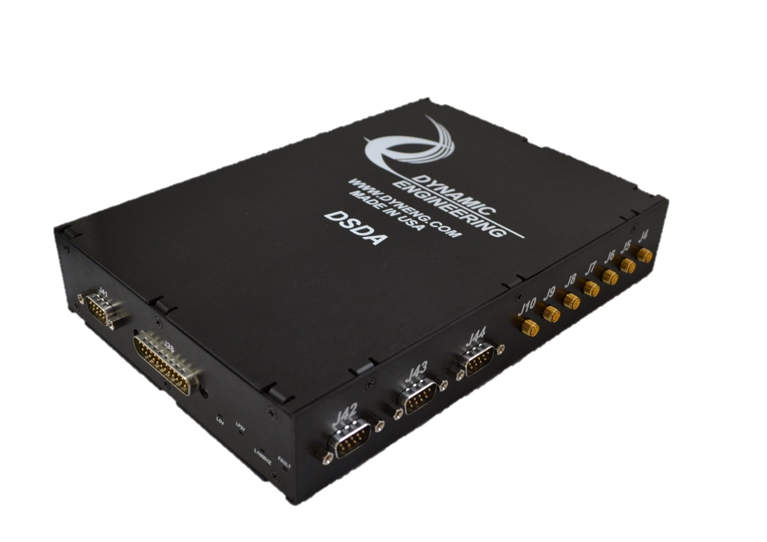
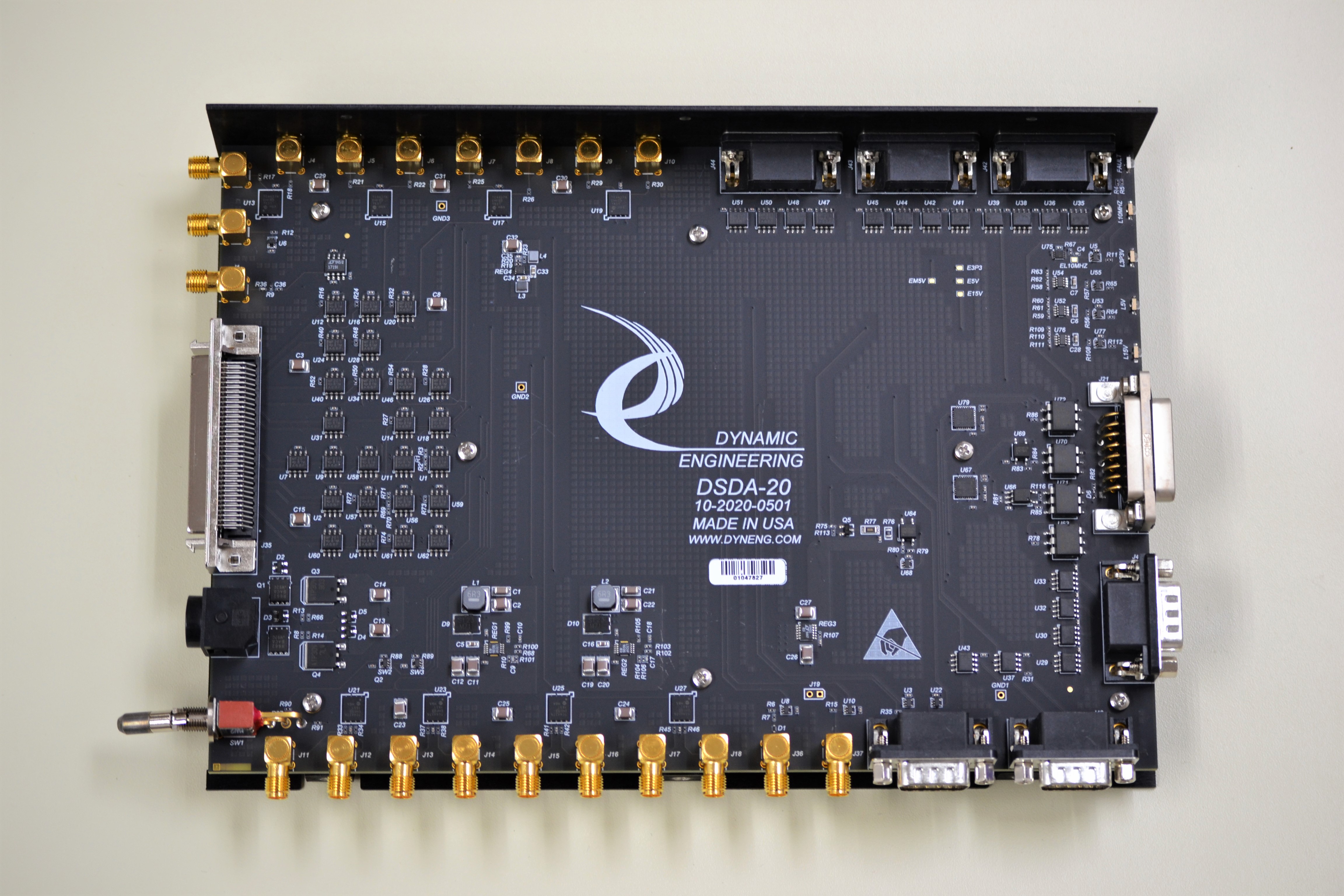
The DSDA Distributed Signal Distribution Assembly is a chassis level design with multiple signal conversions between RS485, LVDS, RS232, TTL, 50 ohm drivers, commutator. Many are opticailly isolated.
IP-CAN has an option to use a combination of galvanic and isolated power supply to provide electrically isolated IO.
IP-Relay16 provides 16 Form C relays for high and low side switching with 1.5A and 220/250 V contact capabilities plus the isolation provided by the relay.
IP-OptoISO-16 provides 16 Optically isolated FET switches with 60V and 1.5A. 4000V RMS isolation.
The DSDA Distributed Signal Distribution Assembly is a chassis level design with multiple signal conversions between RS485, LVDS, RS232, TTL, 50 ohm drivers, commutator. Many are opticailly isolated.
IP-CAN has an option to use a combination of galvanic and isolated power supply to provide electrically isolated IO.
Pulse
Many interface types use a pulsed signal to support communicatation. A pulse interface is programmable to support different duty cycles [width on and width off], time between, number and other parameters. The interface [IO type] can be single ended [TTL, LVTTL, CMOS etc.], differential [RS-485, LVDS, ECL, PECL etc.], or analog. The Pulse generator may be part of a system where the pulse stream is required, or part of a test set-up to simulate or stimulate the user electronics. Multiple pulse streams when coordinated can be used to simulate encoder outputs to simulate circular motion - say a helicopter rotor accelerating, decelerating, and constant speed.
For many applications, hardware simulation is better than running the actual helicopter or vehicle etc. to get the initial design working.
IP-Pulse is a special version of IP-Parallel-IO and can be single ended or differential or a combination. 4 pulse streams supported. Reference SW includes a user interface to manually change the parameters [via keyboard] or through the standard API. Ask to have this one ported to other platforms.
HDLC, SDLC
High Level Data Link Control & Synchronous Data Link Control - subset of HDLC with byte wide data. Can be interoperable with HDLC if byte oriented. Synchronous Clock and Data interface with eight bit flag characters to delineate messages. If the start and end flag overlap a 15 bit sequence can occur [optional] as the ending zero of the completion flag is reused as the first zero of the start flag. LSB first data transfer. CRC is embedded. HDLC can have non-byte boundary data.
ccPMC-BiSerial-VI-ORN1 2 ports of SDLC. Dual Port RAM [circular buffer] for message storage. Separate Rx and Tx spaces. 2 ports of NRZ also included
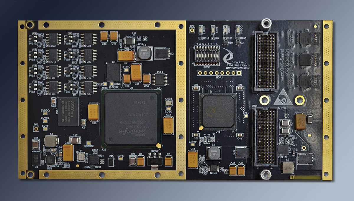
ccXMC-Serial-HDLC 2 ports of HDLC. Dual Port RAM [circular buffer] for message storage. Separate Rx and Tx spaces plus 2 ports of NRZ, and 3 ports of UART
ccPMC-BiSerial-VI-ORN1 2 ports of SDLC. Dual Port RAM [circular buffer] for message storage. Separate Rx and Tx spaces. 2 ports of NRZ also included
ccXMC-Serial-HDLC 2 ports of HDLC. Dual Port RAM [circular buffer] for message storage. Separate Rx and Tx spaces plus 2 ports of NRZ, and 3 ports of UART
ASCB
Avionics Standard Communications Bus. Dual redundant implementation. Multiple revisions with the most recent and likely encountered versions being Manchester encoded [D] and 8B10B encoded [E]. 2 wire psuedo differential system with transformer isolation. Designed for longer cable runs with multiple bulk head connections and taps. 20 MHz rate translates to 10 Mbits with the Manchester version and 16 MBits with the 8B10B due to the encodings. In use with small and medium size aircraft to communicate with the navigation and other systems for operation and test.
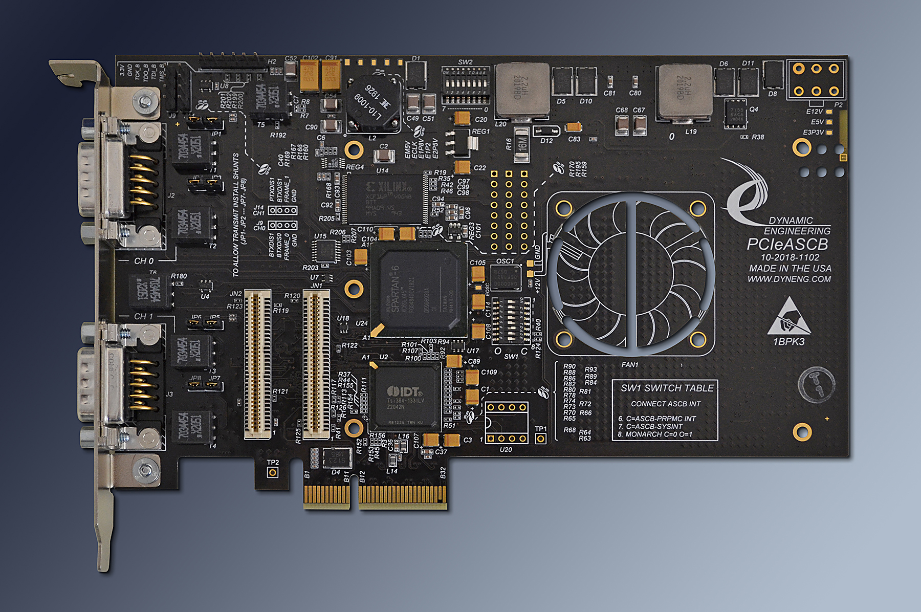
PCIe-ASCB - PCIe module with dual redundant ASCB function - programmable for D or E mode operation. PMC position for use with with PrPMC device.
PCI-ASCB - PCI module with dual redundant ASCB function - programmable for D or E mode operation. PMC position for use with with PrPMC device.
PCIe-ASCB - PCIe module with dual redundant ASCB function - programmable for D or E mode operation. PMC position for use with with PrPMC device.
PCI-ASCB - PCI module with dual redundant ASCB function - programmable for D or E mode operation. PMC position for use with with PrPMC device.
HaveQuick
Time-of-Day interface. HaveQuick protocol uses a 1PPS signal plus data interface to broadcast Hours, Minutes, Seconds, Day of Year, 2 digit year and a figure of merit. Manchester Encoded BCD data plus modified Hamming code with 4 data bits and 4 check bits for each digit sent.
IP-HaveQuick can receive and transmit HaveQuick format data. The time is programmable - in master mode the user can set the initial time and the hardware broadast automatically. Read the current time anytime. Supports fast back-to-back accesses to allow use with IP carriers supporting 32 or 64 bit accesses.
IP-HaveQuick can receive and transmit HaveQuick format data. The time is programmable - in master mode the user can set the initial time and the hardware broadast automatically. Read the current time anytime. Supports fast back-to-back accesses to allow use with IP carriers supporting 32 or 64 bit accesses.
Software
Operating Systems
Current OS support include Windows® 10/11, Linux, and VxWorks.
Languages
C/C++ are the primary languages used for driver and user application/reference software development, as well as VHDL/Verilog for FPGA design. Our software engineers also have extensive experience developing APIs to allow customers to integrate code bases in other languages, such as, Python or JavaScript.
Driver
Drivers are implemented at the kernel level to ensure optimal performance and clean integration with relevant operating system for controlling the hardware. In some cases, user space APIs are coupled with kernel drivers to simplify integration of the device into existing code bases.
Application
Drivers are coupled with reference software which is also used inhouse to test associated hardware. The reference software ("UserAp") demonstrates the functionality of the hardware - DMA for example - and should allow those who purchase the hardware to get up and running with software integration quickly. In addition, we often provide client requested functionality - file / data movement, processing, algorithm implementation etc.
Memory
Some types of memory are direct - FIFO for example. Other types require management - circular buffers etc. The management aspect can be implemented at the Driver / Application level depending on the hareware/client specifications.
Documentation
All drivers/reference software are accompanied by a software manual. The manual details how to install the drivers as well as the API for the driver. In addition, headers and in-line comments are provided throughout the reference software to give greater details on API usage. Our Linux software also provides instructions for launching the reference software as launching the CLI application often requires passing parameters at execution.
Interrupts
The driver handles the interrupts and works with the application to control the process. For example the end of transfer interrupt with DMA or the end of transmission interrupt. Most hardware implementations have multiple possible interrupts. The software architecture for the system being implemented will dictate which interrupts to use, treat as status, or ignore.
What is our experience with Drivers? A Short History
"Necessity is the mother of invention and Repetition is the mother of skill"
In 1988, with 10 years of embedded systems experience under his belt our founder was ready for a change. Dynamic Engineering started out as a hardware consulting company. In order to test our hardware designs, surprise surprise, we needed software. At the time most embedded systems were using assembly, C or a mixture and homegrown or no OS. Development on a PC and cross-compiling to the target 68XXX or 87XX embedded processor was the norm.
When better tools and the PCI bus became available, we transitioned to start testing on the PC. At first, we used a generic driver within the WinRT architecture. After a while our clients began to ask for drivers for Windows® and we responded by our expanding our team to include more software engineers and writing device drivers for NT. The first drivers written were heavily influenced by our client´s requirements in terms of functionality, performance and documentation. Over the course of many, many drivers for PMC, XMC, PCI, PCIe, PC104p, IP and other platforms we have continued to expand our software development team with high level experts and have developed an extensive library of driver components and application software.
With Windows® 2000, Microsoft released a new set of tools and libraries, namely, the Windows Driver Frameworks (WDF) which included the Kernel-Mode Driver Framework (KMDF) Our team adapted to using this framework and has been using various version of the framework as windows has progressed to Windows® 10/11 to ensure drivers optimally control the hardware we provide. As Windows® continued to progress, may of our clients shifted to using Linux directly or indirectly (when coupled with VxWorks) meet their needs. To meet demand, we have continued to expand our software team by adding Linux kernel/driver experts as well. As a result, our current software team can provide high level quality off-the-shelf or customized kernel and user level software or APIs to support their hardware integration.
Dynamic Engineering is now in the position of being skilled with driver writing and testing. It has been said that it takes 10,000 hours to become a master of something. Dynamic Engineering has multiples of this metric.
Bottom Up or Top Down?
Over the years the distinction between hardware and software has blurred. You can do more in VHDL or more with the driver/application code. The trick is to do the right amount of each to off-load the CPU as much as possible without requiring an overly expensive hardware set.
We start with some sort of requirement definition. Sometimes this is "Just like but different" referencing another product, and sometimes a full blown specification. Our designs frequently have an FPGA or other programmable device plus drivers plus the application software. The VHDL⬄Driver⬄Application boundaries all affect each other. We frequently start with the VHDL and progress to the driver and then application code - a bottom up approach starting from the top it would seem. We use design experience as our feed-back loop to improve our VHDL to make our drivers easier to write. Things like consistent register definitions, direct rather than indexed access to the registers, independent channels for independent functions; the driver, and consequently the application software are easier to conceive and write. Testing is also improved with fewer interactions between components.
What is a Driver and why do I need one?
A Driver, at its core, is a piece of software that allows user space software to communicate with and control hardware. For example, most hardware consists of a set of registers that tell the hardware how to operate. The driver allows a user space application to set these values. Similarly, a driver allows a user space application to give data to the hardware and controls how that hardware receives the data, such as by using DMA when the side of the data is sufficient to warrant the overhead cost of using it. For performance and proper integration reasons, many drivers are implemented in kernel space. While in some cases user space drivers are possible, the complexity of the hardware developed by Dynamic Engineering, e.g. supporting DMA or operating on the PCI&47;PCIe bus, requires kernel space drivers. Thus, in some sense, our drivers can be seen as something added too, or connected to, an operating system’s Kernel to expand the kernel functionality to control hardware it would otherwise not know how to control.
It is also important to know that not all driver architecture is the same. Some driver architectures favor raw usage of the hardware whereby each call to the driver only performs a single task (such as writing/reading a register). By contrast, some architectures tend to try to abstract away much of the complexity of the hardware by simplifying the API and only allowing users to perform a limited number of calls that, in turn, perform several tasks for each call. At dynamic engineering we generally try to provide both types of access simultaneously. This is achieved by creating a set of common calls to the driver that perform multiple steps at the kernel level and allow easy use of the hardware, such as open, read, write, close, poll, etc. At the same time, we also provide a large set of simple calls that give the user full control and access to every bit in the hardware. Our architecture concept is aimed to allow users to get up and running quickly while not constraining the ways an expert may want to use the hardware. However, because a single call that performs multiple function in kernel space provides optimal performance by limiting context switching, we also offer the option of creating custom calls and drivers for specific use cases.
Lastly, since the driver is operating in kernel space it is easy to have the driver "break the system" and cause a blue screen or or kernel crash. As such, it is important to get the driver right. Dynamic Engineering has intimate knowledge of the HW and a lot of experience with the OS to make sure our Dynamic Drivers are written properly and tested thoroughly before the client receives them. Debugging drivers is a difficult task. As the hardware designer we have the ability to see what is happening at a hardware level within our VHDL as well as monitoring the driver activity to efficiently debug any issues that do come up to prevent our client from being bitten by a bug. Typically it is in our clients best interest to focus on their system and their application requirements, and better served by leaving the drivers to us.
What about test? How do I get started?
Testing the driver is an important step. The best way to test the driver´s operation is to use the driver to do real world tasks. Each Dynamic Driver comes with a User Application "UserAp" which contains a complete set of C/C++ routines. The UserAp incorporates a menu and routines allowing the user to run the routines with keyboard control. Since the routines are supplied as source files the user can set break-points and observe operation, including parameters passed, counts etc. The routines are written to test the hardware and are used in our manufacturing to do an ATP on the hardware.
It is reccomended that a new user [for a particular type of HW] starts by running the ATP on their hardware. By executing the test software the user can gain confidence in the hardware set-up, and in the case of some issue - DMA not being enabled on their computer etc. - it is easier to work it out with a known good set of software. Once the routines are running, the user can make changes to the routines to more closely mimic their system requirements. Through this process the user can become familiar with the calls, where to find them, how to compile altered software and so forth. It is encouraged to reuse our software as much as makes sense for your system.
In our reference software, adding tests is easily accomplished to help our users add relevant tests to our software before integrating that same functionality into their system. By testing with our software first the user is no longer operating with blind hope that the software will work correctly within their system. This is key because the user can ensure what they want to accomplish with the hardware is possible independently before implementing this functionality into incomplete code. Most importantly, we design our reference software specifically with the knowledge and understanding that many of our clients have already benefited from this specific format and functionality, so we have strong evident that our concept works for our users.
With our software package, we also demonstrate that multiple cards can operate together within a single system. For example, if you have two PMC-SpaceWire cards, the software will number them 0 and 1 and show you how you can control multiple cards within a single code base. In this case, position within an IP carrier or the DIP Switch on the board can be read to allow the user to associate a particular board with a unique ID to ensure the correct device is being operated on.
Don´t you hate it when you get a new piece of hardware and then realize you have no idea where to start and the documentation that sounded good on the website seems not to apply to what you want to do? With the software provided to support your hardware purchase you can have a "quick start" and many times be running the test software that first day. Installing the driver is easy with almost Plug and Play operation. Starting the reference executable is a double-click or short command away. The menu system is intuitive. In many cases you can open our project with your editor and see the structure.
The test software is not your typical "reference software" - it is in active use in our manufacturing facility so you know it is something to depend on.
With a tech support mini-contract in place, our engineers can support you by adding new calls or reference cases to execute on the hardware. Confidence in your set-up and reference cases will have you making progress rapidly. A small investment in support can pay large dividends.
What do I get?
The "Driver" has several components as part of the deliverable package.
The Dynamic Driver fileset includes the Device Driver which is either an executable [.sys and .inf or similar] or the source in the case of Linux. The UserAp is delivered as source code. We use Visual Studio (for Windows®) to develop. If you have the same software you can open the project directly. If not you will need to recompile into your tool set. Within the UserAp are the include [.h] files to tie the application software to the driver. The include files contain the Driver Call definitions (i.e. the API). The software manual also defines the Driver Calls. The Software Manual is a PDF located on the Dynamic Data Sheet for the product. Usually located toward the bottom of the DDS.
Typical Files included within the UserAp file set for a particular design.
Please be sure to refer to the manuals for the Hardware and for the Software. The Driver or Software manual has installation instructions and a list of the included driver calls. The Hardware manual has the detailed operational information for the design. Operational concepts, features, address maps, bitmaps, pinouts, loop-back fixture connections, ordering information and more. When using the Driver, many of the calls allow direct access to the bits or to structures to change settings. Detailed information about those settings are contained in the Hardware manual. Even if you are a Software designer, please refer to the Hardware Manual too.
Base, Channels, and Architectural Considerations
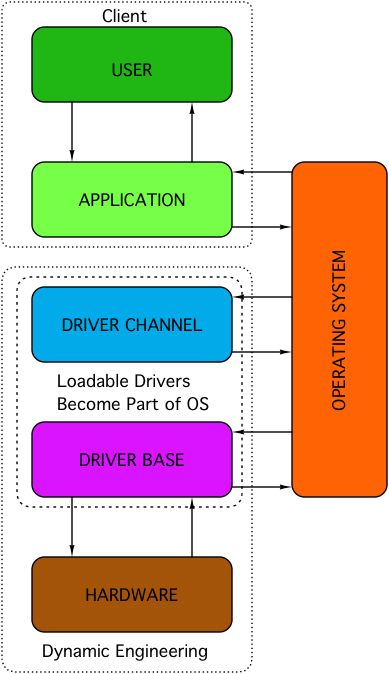 |
The block diagram shows the interaction of the hardware and software, client and Dynamic Engineering as well as a peak at our basic approach to architecture. The hardware is the embedded firmware, PCB and components used in the design. The driver is really several pieces of software that are compiled together to make the "Base" and "Channel" system files. The base is aligned with the general purpose functions of the board. The base module is installed first and facilitates the loading of the channel(s). The channels are the logic associated with a specific function. For example the PMC-SpaceWire design has 4 channels. Each channel is independent of the other channels from a programming model point of view. By breaking the HW into groups that contain a common function - Channels - the software can be much easier to implement for the Driver and for the Application layers. For the Driver it is easier because the same channel software can be called multiple times since each channel is identical - just with a base address offset. This means less software maintenance and fewer places where "accidents" can occur. This also means the corresponding channel application SW can be identical since each channel uses the same calls. For example, the PMC-BiSerial-IV-HW1 has 32 identical channels. The channel number is passed in to differentiate. In cases where the channels have different functions, the channels are loaded with different channel drivers corresponding to those channels. For example the ccPMC-BiSerial-IV-ORN1 has 2 channels each of 2 different functions plus a GPIO function which is loaded in the base driver. |
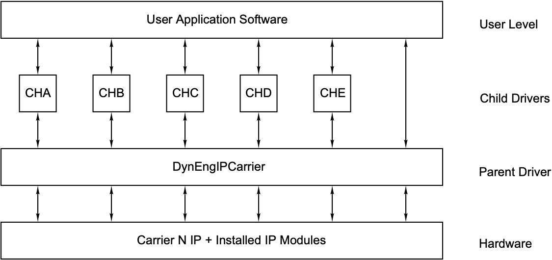 Another interesting architectural situation occurs with IndustryPack® Carriers and installed IndustryPack® modules. The carrier driver will be loaded first and needs to determine the cards loaded onto the carrier. The carrier driver will need to load the correct driver for each IP device found. With a Windows® system the information about which slot is being enumerated and associated with which instance of the driver is lost once the load process is completed - Windows® does not make this information easily available at the driver level. Dynamic Engineering uses a Parent - Child approach with the IndustryPack® modules written for the specific module type and the carrier driver written to handle the differences between the various IP Module carriers that Dynamic Engineering manufactures. cPCI(2 and 4 positions), PCI(3 and 5 positions), PCIe(3 and 5 positions), PC104p(1 and 4 positions), VPX(2 positions). This approach means that the IP Module driver is the same for all of our carriers. This also means that Application software written for a specific module is easily ported to a different carrier, or even chassis configuration.
To solve the issue of knowing which instance of which card is in which slot on which carrier , the carrier driver writes the information to a special file passed to the child driver. Once the Child driver is loaded for that instance it can read the data. The carriers have an 8 position DipSwitch installed which allows up to 256 of the same carrier type in system. Between the carrier name and stored code in the IP the designer has unambiguous knowledge of which instance of the driver is controlling which piece of hardware for multi-board and multi-carrier systems. This is important for obvious reasons - it would be a real bummer if you are controlling the wrong "Launch Control".
We have taken a similar approach to operate with Linux. Again the IP Module drivers can be used on any of our IP Module Carriers, and you have deterministic operation from a driver instance to hardware point of view.
Dynamic Engineering uses the DIPSwitch approach on all of our PCI/PCIe based designs to allow for multi-card operation or for whatever purpose the client decides. Simple and effective. Full disclosure: we had the necessity for a solution after designing the PMC-Parallel-IO card - our first PMC. All other PMC, XMC, PCI, PCIe, PC104p, VPX etc. cards with a dynamic addressing scheme have the DIPSwitch feature.
When designs incorporate the ability to load the user compiled FPGA data into the HW at run time, additional interesting architectural quandaries arise. Dynamic Engineering has taken the approach that we need a consistent simple to use method of handling this situation across platforms. As a result our drivers can auto-load FPGA code from the hard drive at run time, interrogate the loaded HW and determine which driver to load to match the installed FPGA load. In addition we provide a mechanism to make a call from the application level to reload the design with a file, and again auto-load the design driver based on what was installed.
Since our hardware will be used along with other companies designs the situation will come up where the installed design or HW does not match any design number in our system. When this happens we install a Generic Driver to allow the user to access the hardware by providing the address and data information for writes, and address information for reads. Interrupts are handled as well. IP-Generic comes with the IndustryPack® Carrier driver, PCIe-AlteraCycloneIV, PMC-XM series, cPCI-DARTBase, etc. come with a generic driver specific to those designs.
Necessity really is the catalyst for invention. This discussion has scratched the surface of the innovations and architectural features of Dynamic Drivers. Please contact us for more information or read the manuals located on each Dynamic Data Sheet.
Layout
Dynamic Engineering products are industrial strength with strong attention to detail - Schematic design, FPGA design, SW design, and to glue it all together the Layout design and manufacturing processes.It all starts with the PCB [Printed Circuit Board]. Quality design and quality materials are required to meet the strenuous requirements of many of our implementations. You can do the job quickly or you can do the design correctly. We pride ourselves on taking the time to put the extra work into our layouts. The quality goes in before the parts go on. In addition to routing strategy and layer counts, Via size, plating requirements, break-out trace widths, and materials are areas where quality comes into play.
The via size and method of trace attachment to the via affect the signal shape and reliability. Using tear-drop trace connections to pads, vias and through hole components enhance the reliability and minimize the impedance discontinuity resulting in a cleaner signal. Via size selection to enhance reliability while providing enough copper for power distribution [with low temperature rise] and sufficient surface area to bond to where traces are interconnected. Enhanced vibration endurance than smaller vias and traces is afforded with this methodolgy.
The design may have several power planes. Each must have sufficient copper weight and coverage to provide the references required for the routing plus the current and voltages needed by the various devices on the board.
Specifications for various IO standards or buses are not necessarily the same in terms of implementiation on the PCB. Part of the design process is to determine the correct stack-up to minimize layers while providing proper reference planes to incorporate all of the impedance requirements. For example the PCI interface has a published set of requirements for compliance which restrict length, impedance, loading and other factors - it is a single ended bus and the specification is pretty loose 60-100 ohms. Dynamic Engineering has adopted the cPCI specification for PCI implementation with a 65 ohm target and much tigher tolerances. With PCIe the bus is a mixture of differential and single ended signals. The differentials are 100 ohms. In a mixed system we will have 100 ohm, 65 ohm, and other impedances to control. The combination of width and distance from the plane are used to manage the impedance. By controlling all layers to the same targets the signals with vias do not see the same discontinuities as on boards with wider tolerances between planes.
The Dynamic Engineering approach to matched length situations is to over match to put as much errror budget as possible into the user side. By doing this our interfaces frequently work in situations where other hardware with looser specifications does not. For example we tend to match to the mil even when you can match to much less restrictive tolerances. If you are going to match the signals you might as well match them. The current Dynamic Engineering standard is to use curved traces everywhere including length matching spaghetti.
Currently Dynamic Engineering is using Altium 3-D layout software. The models created directly from the layout can be used with our SolidWorks design package in Mechanical Design for chassis, bezels, and othe rmechanical items.
Dynamic Engineering Mechanical Design Examples
 |
Dynamic Engineering´s expertise in mechanical design includes ruggedized enclosures, EMI chassis and modules, thermal dissipating chassis [conduction and convection], and modules [conduction and convection], rack mount chassis, test equipment and flex circuits. Commercial, Industrial, and Mil-Spec designs. Our primary tool for Mechanical Design is SolidWorks. Dynamic Engineering frequently colaborates with our clients by sharing STEP files to support design modifications and manufacturing of clientized versions of our products or new custom mechanical aparatus. |
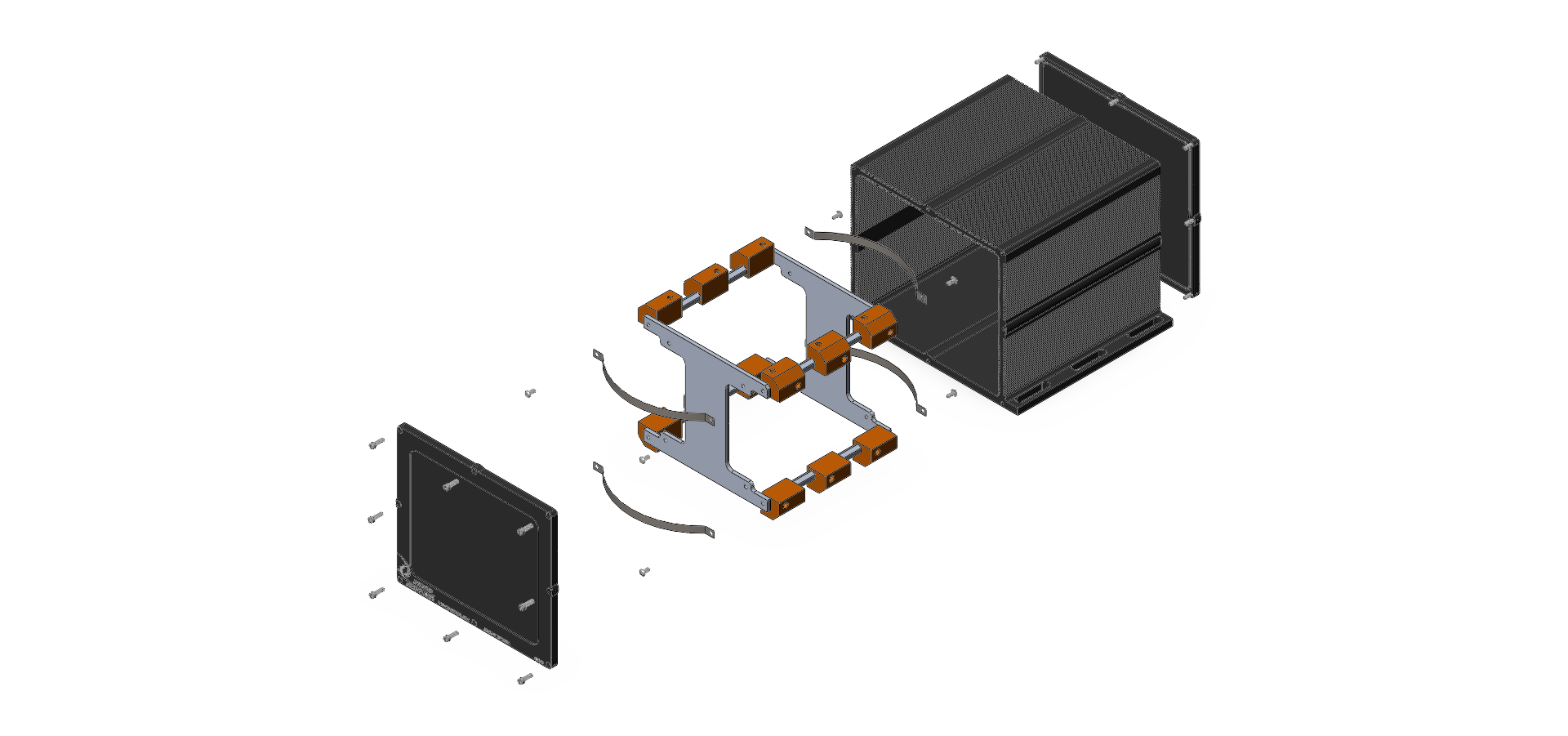
PC104, PC104p, PCI-104, PCIe104 chassis
Dynamic Engineering chassis to support rugged mount applications for PC/104p, PC/104, PCI-104, and PCIe104 applications. Forced air or conduction cooled.
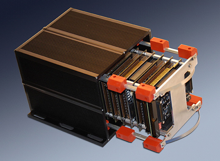
PMC Mini Chassis with 2 positions shown
Dynamic Engineering chassis to support PMC applications needing 2 or 4 PMCs. Forced Air.
 |
 |
Client design with controlled impedance interface between connector types. Custom chassis design.
Client supplied sketch and pinout. Dynamic Engineering supplied schematic, layout, mechanical design and finished product.
 |
 |
Client design with conversion between LVDS and 50 ohm, single ended and LVDS, commutator and LVDS. Local power supply with reverse power protection. Controlled impedance. Custom chassis design. Pads for PCB, SolidWorks for chassis.
Client supplied sketch and pinout. Dynamic Engineering supplied schematic, layout, mechanical design and finished product.
 |
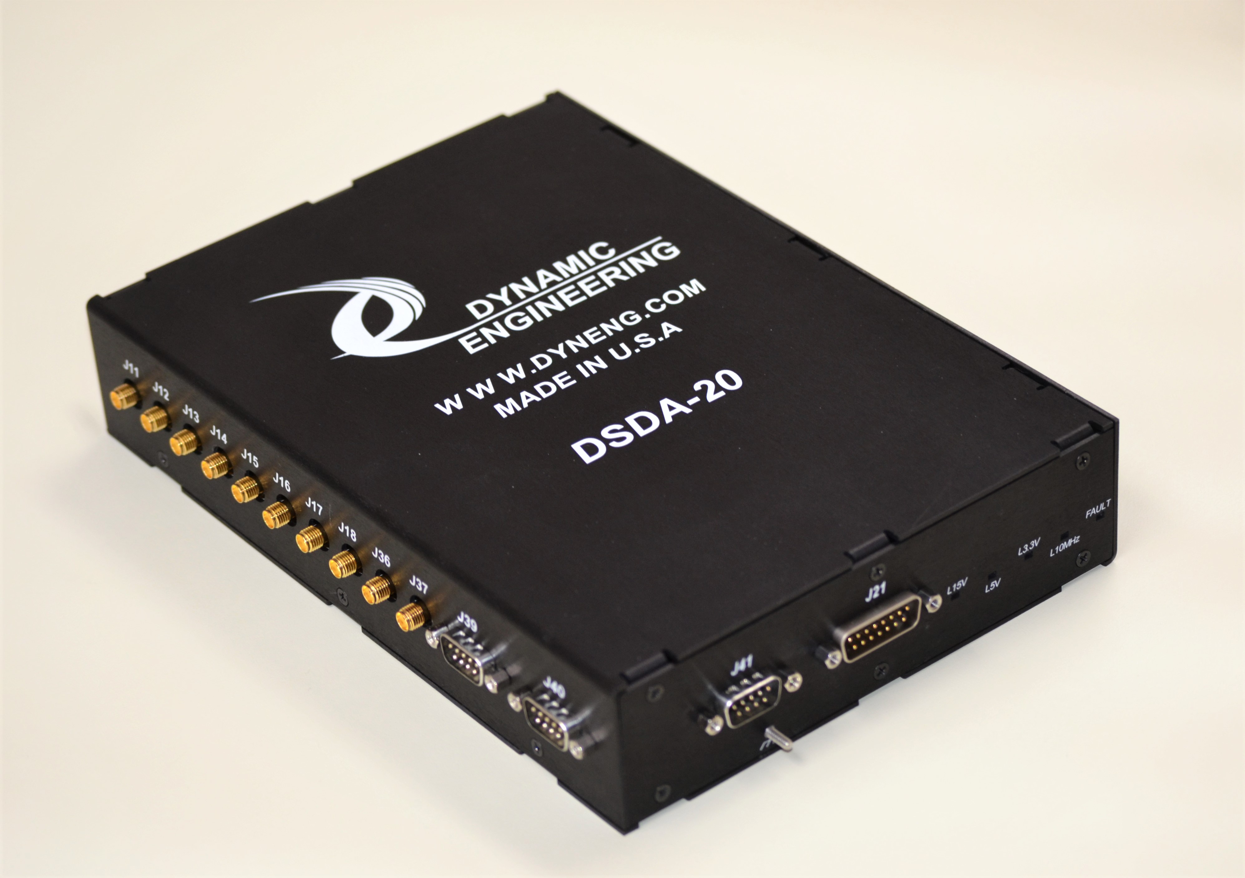 |
The Discrete Signal Distribution Adapter has several implementations [4 so far] including the original DSDA and the more recent DSDA-20 version. The designs incorporate Chassis, PCB, Power Supply, and signal design.
These designs do a bit of everything and would be a great starting point for your project.
DSDA-20 NSN = 5998-01-697-5448
DSDA-II NSN = 5895-01-688-9843
DSDA-II-GN NSN = 5895-01-694-6933
UltraMask Tape application system for applying paper and tape to windows and other surfaces for masking purposes. Handles Paper and Film. Dynamic Engineering Co-authored Patent #5,470,430.
Hardware Design
The Embedded Engineer is lthe quarterback of the design process. The engineer applies their knowledge to the specification and decides on the path forward, works with management to assign the appropriate resources to successfully implement the plan, and executes the plan. Taking the specification through design and into manufacturing.The schematic is the glue that holds the design together allocating the design requirements and incorporating the circuits. Thought must go into planning and implementing to incorporate features to allow the design to meet the requirements both specified and implied. For example, test, physical space, EMI, and thermal considerations.
Frequently the schematic design incorporates features which require mini-designs to implement - DC/DC power supplies can require quite a bit of spread sheet work to select optimal components that are actually available. If the design incorporates an FPGA or CPU etc. those devices often require a side development of their own with some recursion to optimize the pinout and layout which still meeting timing requirements.
With the initial schematic complete the design can be specified for layout requirements - impedance, length matching, form factor, special requirements for conduction cooling, EMI, and other considerations. Working with layout the PCB is designed and checked against the requirements. PCB design adds another dimension - manufacturability. Usually a manufacturing engineering is part of the layout process to make sure the output from engineering can be manufactured efficiently.
Hardware design continues as the design must be fully tested as part of the FAI process - first units are built and checked with AOI and XRAY equipment to insure the process for manufacturing is properly dialed in and the FAI units released to engineering are not going to waste engineering time with shorts and opens under devices etc. The design is tested and the focus usually shifts to the FPGA and Software aspects of the design. Software is written to stimulate the various modes to allow testing against the requirements of the design. As the software is developed the FPGA is updated to correct design issues or add new features that come to light during the testing process. Perhaps a feature to make testing the IO easier for manufacturing or programming for our software team or client more efficient.
Once through T&I the design can be released to manufacturing to complete the FAI by running the ATP on the hardware within the Manufacturing space.
FPGA
Xilinx [AMD], Altera [Intel], Lattice, Micro-Semi [Microchip]
Languages
VHDL/Verilog for FPGA design. Extensive in house library [mostly in VHDL]
Power Supplies
LDO, DC/DC [Buck, Boost, Buck-Boost] are the most common local supplies. Multi-phase buck converters designed for larger power requirements
IO electrical
Single ended [TTL, LVTTL, CMOS, RS232, 50 ohm, Discrete, etc.], differential [LVDS, RS485, RS422, PECL, NECL, 1553, 429, etc. ], analog [A/D, D/A, commutator, etc.]
IO Protocol
HOTLink, SpaceWire, UART, Wizard Link, Manchester, Miller, ASCB, HaveQuick, NRZ, NRZL, ARINC 429, MIL-STD-1553, CAN, GPIO, SDLC, and many custom interfaces.
CPLD
Xilinx, Lattice
Memory
DDR plus controller (circular buffer manager with 8 programmable segments within FPGA) for multiport access with FIFO interface for drop in design improvement. FIFO and Dual Port RAM with internal block RAM [FPGA resources]
CPU
Lots of experience dating back to the 68000 family. Current designs incorporating T1042 [NXP] -
Interrupts
HW options for interrupt generally include end-of-transmission, end-of-reception, Memory above a programmed level, Memory below a programmed level, error conditions, time-tick, special events based on the design. Master interrupt enable and separete interrupt enables to allow polling of some or all of the status instead of use as interrupts. Usually latched with clear by write-back
Documentation
HW manual with memory maps, bit maps, description of operation, pinouts, loop-back connections etc.