Made in USA
The Embedded Solutions Experts
PCIe8LXMCX2HL
PCIe adapter for XMC with 2 XMC positions - Customized rear IO
PCIe8LXMCX2HL Description
- Industrial Temperature
- PCIe 1-8 Lane Interface
- 2 XMC Positions with PCIe Interface Supporting Gen1(2.5 Gbps), Gen 2 (5 Gbps), Gen3 (8 GTS)
- Plug and Play operation
- Local Power Supply for 3.3, 5 and -12V Operating from System +12V
- Full Length PCIe Card
- "Zero Slot Fan"™ Compatible
- Bezel I/O and customized Jn4 I/O for both XMCs
- 1 Year Warranty Standard. Extended Warranty Available.
- ROHS and Standard Processing Available

Embedded applications frequently require real time processing coupled with special purpose IO. With PCIe8LXMCX2HL´s two positions a PrXMC can be matched with another XMC to make a high bandwidth processing node. The PrXMC can communicate with the host for set-up, and then use the switch to interconnect with the special purpose IO card. With a local processing node of this nature you can use many in parallel with only one computer to provide the system management. For example - 10 in an expansion chassis without overloading the buses or management system.
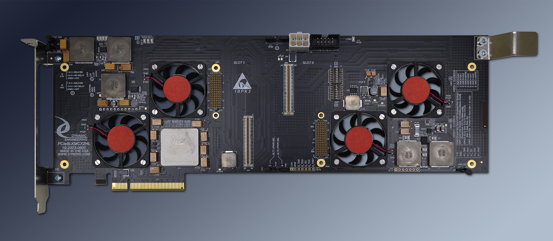
A powerful PCIe 32 lane switch is at the center of the PCIe8LXMCX2HL design. The switch has many capabilities including operating from 1-8 lanes, operating at Gen 1, Gen 2 or Gen3 or mixed IO rates, supports lane reversal and polarity inversion. Support for max payload size transfers up to 2048 bytes ea., fully compliant with the PCIe base specification. The switch has 8 PCIe lanes connected to the PCIe "gold fingers" and 8 to each of the XMCs. The PCIe reference clock is buffered with a Gen1/Gen2/Gen3 compatible clock buffer. The clock buffer is specifically designed to handle spread spectrum and rate locked clocking operation. The buffered clocks are routed to the switch and the two XMC positions. A local power supply and heavy filtering insure stable power and reliable operation for the switch. The PCIe lanes to/from the switch are routed per PCIe specifications with matched lengths and impedance control.
PCIe8LXMCX2HL (PCIexpress Bridge PMC 2 slots HOTLink Rear IO) adapter / carrier converter card provides the ability to install two XMC cards into a standard PCIe slot. Slots with 8 or more lanes are compatible - 8, or 16 for example. PCIe8LXMCX2HL has two XMC card positions. XMC operation with 2.5/5/8 Gbps. PCIe8LXMCX2HL can act as a transparent switch or be programmed to allow private operations on the back side [PCIe] bus.
XMC user IO connector Jn4 from both positions is routed to a 20 position right angle SMT connector with 8 differential pairs. In addition single ended signals are brought to 3 headers to support secondary bus signals - strobes, time, or other control. The XMC front panel connector for slot 1 is mounted though the PCIe mounting bracket.
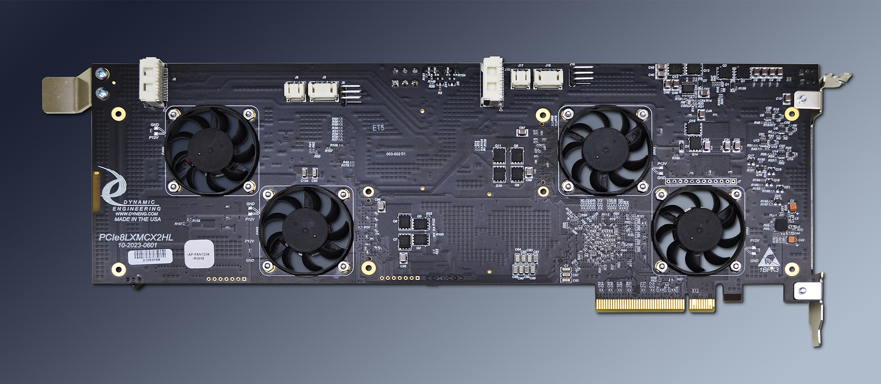
For superior performance PCIe8LXMCX2HL has two cooling cutouts per position for increased airflow to the XMCs. If your application requires a fan you can order PCIe8LXMCX2HL-FAN( ) to have fans mounted to your PCIe8LXMCX2HL. FAN positions are numbered 1-4, position 1 is closest to the PCIe Bezel [left edge in the picture above.] One fan can be mounted per position. Fans can be mounted to blow onto the XMC or to pull air from the XMC (R option.)
The -12V, 5V, and 3.3V for the XMC are regulated on board. The power supply designs utilize switching regulators controlling a MOSFET to convert 12V. An LC filter ensures clean power at the XMC. The Switch/Clock Buffer uses a small amount of 3.3V plus .9V and 1.8V derived from +12. The PCIe gold fingers are rated for 1.1A each, and a total of 5.5A on the +12V rail. 55W are available to the XMCs after power conversion. Please note this is the combined power requirement across the +12, -12, +5, and 3.3V power used by the XMCs. In most cases 55W is sufficient. PCIe8LXMCX2HL includes has a cable connector to allow additional 12V power to be added to the card. The two 12V supplies are DIODE coupled. In some cases the 12V supply on the backplane will not be adequately routed by the PC causing voltage sag on the 12V. If this occurs use the cable connector to compensate. Standard 2x3 PC connector.
The power supplies include the bulk capacitance to properly bypass the FETs and post conversion voltage rails. In addition the XMC connectors are bypassed with a .1 uF capacitor at each power pin. The power supplies are checked with voltage monitor circuits. The LEDs are not illuminated unless the voltage is within the defined range. Two headers allow user selection of 5V and 3.3V power on characteristics. The user can select [with shunts] Instant On, Delayed On, and disabled. If your design does not use one of the rails you can turn it off. If your system enumerates early in the power up cycle you can select instant on. If your system can use the delayed load on the power supply to advantage select delayed. 5V and 3.V supplies are rated 15A.
The XMC specification calls out "VPWR " which can be either 12V or 5V. PCIe8LXMCX2HL has FET switching and a header to allow user selection of either 12V or 5V or neither voltage to be supplied to these 8 pins [per XMC]. The selection is separate per XMC position. Build options are provided to allow "pre selected" voltages on these pins without the headers. The 12V asnd 5V supplied are part of the same power budget mentioned above. It is suggested the user select the rail definition most efficient for use, alternatively based on noise, the 5V will likely be quieter since it is converted on board and isolated from the 3.3V rail.
The signals routed from pins on the Jn4 (PN4) connector for each position are routed with matched length, impedance controlled differential traces suitable for single ended and differential operation.
The XMC JTAG connections for position 0 and position1 are routed to separate headers centrally located between the XMC devices. Please let us know if you want this header installed. [-JTAG12]
The PCIe bus does not have a concept of global addressing. A DIPSWITCH is provided to allow the user to select the Global Address on both XMC positions individually.
A powerful PCIe 32 lane switch is at the center of the PCIe8LXMCX2HL design. The switch has many capabilities including operating from 1-8 lanes, operating at Gen 1, Gen 2 or Gen3 or mixed IO rates, supports lane reversal and polarity inversion. Support for max payload size transfers up to 2048 bytes ea., fully compliant with the PCIe base specification. The switch has 8 PCIe lanes connected to the PCIe "gold fingers" and 8 to each of the XMCs. The PCIe reference clock is buffered with a Gen1/Gen2/Gen3 compatible clock buffer. The clock buffer is specifically designed to handle spread spectrum and rate locked clocking operation. The buffered clocks are routed to the switch and the two XMC positions. A local power supply and heavy filtering insure stable power and reliable operation for the switch. The PCIe lanes to/from the switch are routed per PCIe specifications with matched lengths and impedance control.
PCIe8LXMCX2HL (PCIexpress Bridge PMC 2 slots HOTLink Rear IO) adapter / carrier converter card provides the ability to install two XMC cards into a standard PCIe slot. Slots with 8 or more lanes are compatible - 8, or 16 for example. PCIe8LXMCX2HL has two XMC card positions. XMC operation with 2.5/5/8 Gbps. PCIe8LXMCX2HL can act as a transparent switch or be programmed to allow private operations on the back side [PCIe] bus.
XMC user IO connector Jn4 from both positions is routed to a 20 position right angle SMT connector with 8 differential pairs. In addition single ended signals are brought to 3 headers to support secondary bus signals - strobes, time, or other control. The XMC front panel connector for slot 1 is mounted though the PCIe mounting bracket.
For superior performance PCIe8LXMCX2HL has two cooling cutouts per position for increased airflow to the XMCs. If your application requires a fan you can order PCIe8LXMCX2HL-FAN( ) to have fans mounted to your PCIe8LXMCX2HL. FAN positions are numbered 1-4, position 1 is closest to the PCIe Bezel [left edge in the picture above.] One fan can be mounted per position. Fans can be mounted to blow onto the XMC or to pull air from the XMC (R option.)
The -12V, 5V, and 3.3V for the XMC are regulated on board. The power supply designs utilize switching regulators controlling a MOSFET to convert 12V. An LC filter ensures clean power at the XMC. The Switch/Clock Buffer uses a small amount of 3.3V plus .9V and 1.8V derived from +12. The PCIe gold fingers are rated for 1.1A each, and a total of 5.5A on the +12V rail. 55W are available to the XMCs after power conversion. Please note this is the combined power requirement across the +12, -12, +5, and 3.3V power used by the XMCs. In most cases 55W is sufficient. PCIe8LXMCX2HL includes has a cable connector to allow additional 12V power to be added to the card. The two 12V supplies are DIODE coupled. In some cases the 12V supply on the backplane will not be adequately routed by the PC causing voltage sag on the 12V. If this occurs use the cable connector to compensate. Standard 2x3 PC connector.
The power supplies include the bulk capacitance to properly bypass the FETs and post conversion voltage rails. In addition the XMC connectors are bypassed with a .1 uF capacitor at each power pin. The power supplies are checked with voltage monitor circuits. The LEDs are not illuminated unless the voltage is within the defined range. Two headers allow user selection of 5V and 3.3V power on characteristics. The user can select [with shunts] Instant On, Delayed On, and disabled. If your design does not use one of the rails you can turn it off. If your system enumerates early in the power up cycle you can select instant on. If your system can use the delayed load on the power supply to advantage select delayed. 5V and 3.V supplies are rated 15A.
The XMC specification calls out "VPWR " which can be either 12V or 5V. PCIe8LXMCX2HL has FET switching and a header to allow user selection of either 12V or 5V or neither voltage to be supplied to these 8 pins [per XMC]. The selection is separate per XMC position. Build options are provided to allow "pre selected" voltages on these pins without the headers. The 12V asnd 5V supplied are part of the same power budget mentioned above. It is suggested the user select the rail definition most efficient for use, alternatively based on noise, the 5V will likely be quieter since it is converted on board and isolated from the 3.3V rail.
The signals routed from pins on the Jn4 (PN4) connector for each position are routed with matched length, impedance controlled differential traces suitable for single ended and differential operation.
The XMC JTAG connections for position 0 and position1 are routed to separate headers centrally located between the XMC devices. Please let us know if you want this header installed. [-JTAG12]
The PCIe bus does not have a concept of global addressing. A DIPSWITCH is provided to allow the user to select the Global Address on both XMC positions individually.
PCIe8LXMCX2HL Features
Size
Full size PCIexpress card with 8 lanes interconnected to the XMC positions via 8x8x8 [24 lanes used with 32 lane] switch. 1-8 lane operation. 8+ lane connector compatible.
XMC compatible slots
2 XMC positions provided.
Clocks
Gen1, Gen2, Gen3 compatible.
Global Addressing
Supported with a user DIPSWITCH
Software Interface
The switch does not require any user set-up. XMC register definitions as defined by installed hardware. XMC register definitions as defined by installed hardware.
Power
Local power supplies provide +5(15A), +12, -12V(4A), +3V(15A) available to XMCs with adequate +12V input current. Supplies use industrial temperature components, and thermal spreading power planes. It is recommended to use the FAN option for high power requirement XMCs. User selectable power supply enable{on/off, delayed, not delayed] for 3.3V and 5V supplies
VPWR
VPWR for each position can be programmed independently. Options for user selection, or pre-selected to 5V or 12V.
Thermal
PCIe8LXMCX2 has cut-outs to support increased airflow over the XMC´s component side. Optional fan(s) with two mounting positions per XMC position are available and recommended for many applications.
Interrupts
PCIe MSI interrupt scheme is supported
IO Interface
XMC Bezel IO supported at PCIe bracket. Jn4 "user IO" supported with 5031482090 SMT differential connector at both positions. 8 Differential pairs per connector. Additional headers to support single ended signals.
Specification
XMC, PCIe specification compliant
LED´s
+3V, +5V, 1.0V, +12V, -12V. LEDs on voltages illuminated via monitoring circuits which check that the voltages are within tolerance.
JTAG
XMC JTAG connections [both positions] are tied to a labeled header. Add -JTAG12 to part number for this option to be installed.
Statement of Volatility
Reliability
TBD hours. Bellcore. GB 25c
STEP
STEP files are available to support your system integration. Please contact sales@dyneng.com for this option.
Export Classification
EAR99, HTS:8537.10.9050
PCIe8LXMCX2HL Benefits
Speed
PCIe8LXMCX2HL offers Gen1- Gen3 speeds plus a second XMC position for designs with more than one XMC. Double the IO in one carrier. When local processing is needed, the rear position can be used with a PrXMC and the IO or signal processing in the front position. The Host computer can set-up operation, and then the PrXMC can use the inter-switch connections for high speed data transfer with second XMC.
Price
Make use of existing XMC designs in PCIe applications without paying for the expense of a new design and layout. Save PCIe slots with two XMCs in one location. Use multiple PCIe8LXMCX2HLs in parallel without overloading your host processor to reduce system cost.
Ease of Use
PCIe8LXMCX2HL is easy to use. The XMCs installed are directly controlled via the PCIe lanes.
Availability
The standard versions are built in quantity allowing for rapid addition of "Zero Slot Fans"™ and other options. Send in your order for rapid delivery.
Size
PCIe8LXMCX2HL is a full size PCIe board which conforms to the PCIe mechanical and electrical specifications. Eliminate mechanical interference issues. PCIe8LXMCX2HL can be used in all full length PCIe compliant slots. Please check that your computer has a full length slot with the proper PCIe offset card guide support.
XMC Compatibility
PCIe8LXMCX2HL is XMC compliant per the XMC specification. All Dynamic Engineering XMC Modules are compatible with the PCIe8LXMCX2HL. All other XMC Modules which are compliant with the XMC specification are compatible with PCIe8LXMCX2HL
PCIe Compatibility
PCIe8LXMCX2HL is PCIe compliant. PCIe8LXMCX2HL can be expected to work in any PCIe compliant backplane with 8+ lane connectors and full length card positions. PCIe8LXMCX2HL has been tested in multiple backplanes.
Part Number: PCIe8LXMCX2HL
Ordering Options
- PCIe8LXMCX2HL Standard board
- -FAN( ) Need additional cooling? Order PCIe8LXMCX2-FAN( ) for a pre-installed 12V 5.2CFM fan(s) to maximize cooling and functionality of your card. The fan has been tested with high wattage PrPMC devices. Fan position 1 is closest to the PCIe bezel. Valid Fan options include: (1,1Rz), (2,2Rz), (3,3Rz), (4,4Rz), low profile fans with fan direction toward XMC or pulling air from the XMC [R]. An additional option is to use standard height fans with more LFM. 8 CFM fans are available as rear mount only (add -FAN(1,2,3,4)R to PN for this option)
- -ROHS Use ROHS processing. Standard processing is "leaded"
- -CC Option to add Conformal Coating
- -VPWR5V Order to receive a PCIe8LXMCX2HL with VPWR forced to 5V instead of user selectable
- -VPWR12V Order to receive a PCIe8LXMCX2HL with VPWR forced to 12V instead of user selectable
- -5VXXX Order to receive a PCIe8LXMCX2HL with 5V supply forced to (replace XXX) No Delay [ND], Delay[DEL], Off[OFF] instead of user selectable
- -3VXXX Order to receive a PCIe8LXMCX2HL with 3.3V supply forced to (replace XXX) No Delay [ND], Delay[DEL], Off[OFF] instead of user selectable
- -AP Order to receive a PCIe8LXMCX2HL with a high power connector installed for supplemental power. 2x6 Standard PC style power supply cable mate.
- -JTAG12 Add JTAG headers for position 0 and position1. Located between the XMCs. Silkscreen labels for pins..
PCIe8LXMCX2HL Drivers
Software Support for PCIe8LXMCX2HL is not needed. PCIe8LXMCX2HL is a switch based card, the drivers and application SW associated with the XMC will not need changing based on using this carrier.
Please see the XMC Driver manual for the specifics of operating the installed device.
Please see the XMC Driver manual for the specifics of operating the installed device.
PCIe8LXMCX2HL Manuals
PCIe8LXMCX2HL Hardware Design Manual Main product manual with example use, pinouts, specifications and more.