Made in USA
The Embedded Solutions Experts
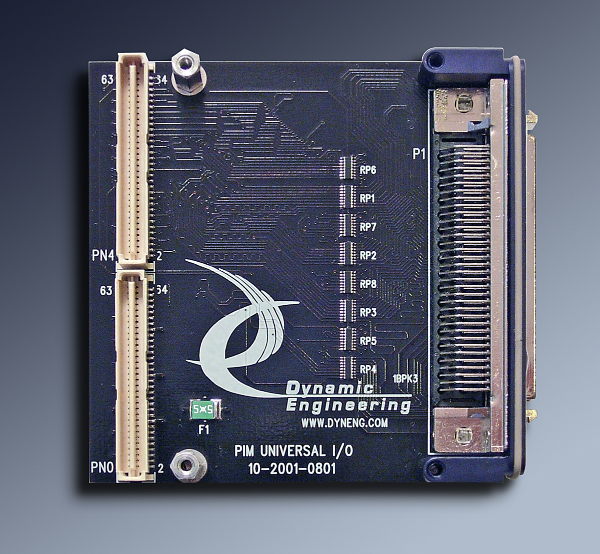
PIM-Universal-IO
PMC Interface Module with 64 1:1 connections for rear IO
PIM-Universal-IO Description
- Use PIM to route PMC/XMC signals for rear panel applications
- Matched length impedance controlled IO
- SCSI connector at rear bezel. SCSI cables and DIN Rail breakouts available
- 1 year warranty standard.

PIM-Universal-IO facilitates rear panel IO in cPCI based systems using PMCs and XMCs. Instead of trying to connect wires to the backplane pins, PIM-Universal-IO provides a method of connecting rear panel IO from a carrier to the rear IO panel. The IO from Jn4/Jn6 is routed to the cPCI connectors allocated to rear IO. The PIM carrier mounts on the underside of the motherboard with the PIMs acting like mini PMCs/ PIM-Universal-IO interconnects the rear panel IO to a SCSI connector. PIM-Universal-IO can be used with any PMC implementing "Pn4" IO.
PIM-Universal-IO uses 1:1 routing to the SCSI connector for the 64 PMC connections. The IO is matched length, and impedance controlled. In addition options are available to add non-zero impedance values on each line. front panel IO where rear panel IO is desired.
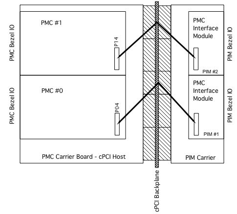
PIM-Universal-IO is part of the PMC family of modular I/O components. The purpose of the PIM-Universal-IO is to facilitate rear panel IO in cPCI systems. The Pn4 "user IO" on the PMC is routed through the host "carrier" board to the backplane. A PIM Carrier is mounted to the underside of the backplane. The Pn4 IO is passed through the backplane connectors to the PIM Carrier and to the installed PIM devices. Most PIM Carriers have two PIM sites which correspond to the two PMCs mounted to the 6U host card. The PIM (PMC Interface Module) carrier supports the flexible PIM scheme for PMC rear I/O.
When installed, PIM-Universal-IO will re-create the PMC Pn4 IO in the rear compartment of the chassis [under the backplane]. All of the 64 IO connections are routed to the 68 pin SCSI II connector. The signals are routed through 0 ohm resistors. Alternate resistor values can be used to provide signal damping.
The PIM specification provides for power and ground references. The ground reference and power are used to tie into internal planes used as references for the signals routed across the PIM. All 64 IO are routed 1:1 to the PIM bezel connector. The extra 4 pins are used for +5V and ground reference. The +5V is fused with a "self healing" fuse. Two signal grounds are provided. Please refer to the tables in the manual for the connector definitions. For custom versions please contact Dynamic Engineering. Examples: (1)a PIM with a different connector to match your PMC and/or different connections, (2) A breakout board with IO specific connectors - perhaps directly on the carrier eliminating the PIMs.
The SCSI connector has a variety of mates available to allow ribbon, discrete, pre-made and customer made cabling solutions.
To order a "complete system" you will need:
2 PIMs
1 PIM Carrier
2 PMC boards
The PIM-Universal can be customized to work with any PMC board.
The PIM-Universal is recommended for Dynamic Engineering PMC designs or any 3rd party product.
PIM-Universal-IO uses 1:1 routing to the SCSI connector for the 64 PMC connections. The IO is matched length, and impedance controlled. In addition options are available to add non-zero impedance values on each line. front panel IO where rear panel IO is desired.
PIM-Universal-IO is part of the PMC family of modular I/O components. The purpose of the PIM-Universal-IO is to facilitate rear panel IO in cPCI systems. The Pn4 "user IO" on the PMC is routed through the host "carrier" board to the backplane. A PIM Carrier is mounted to the underside of the backplane. The Pn4 IO is passed through the backplane connectors to the PIM Carrier and to the installed PIM devices. Most PIM Carriers have two PIM sites which correspond to the two PMCs mounted to the 6U host card. The PIM (PMC Interface Module) carrier supports the flexible PIM scheme for PMC rear I/O.
When installed, PIM-Universal-IO will re-create the PMC Pn4 IO in the rear compartment of the chassis [under the backplane]. All of the 64 IO connections are routed to the 68 pin SCSI II connector. The signals are routed through 0 ohm resistors. Alternate resistor values can be used to provide signal damping.
The PIM specification provides for power and ground references. The ground reference and power are used to tie into internal planes used as references for the signals routed across the PIM. All 64 IO are routed 1:1 to the PIM bezel connector. The extra 4 pins are used for +5V and ground reference. The +5V is fused with a "self healing" fuse. Two signal grounds are provided. Please refer to the tables in the manual for the connector definitions. For custom versions please contact Dynamic Engineering. Examples: (1)a PIM with a different connector to match your PMC and/or different connections, (2) A breakout board with IO specific connectors - perhaps directly on the carrier eliminating the PIMs.
The SCSI connector has a variety of mates available to allow ribbon, discrete, pre-made and customer made cabling solutions.
To order a "complete system" you will need:
2 PIMs
1 PIM Carrier
2 PMC boards
The PIM-Universal can be customized to work with any PMC board.
The PIM-Universal is recommended for Dynamic Engineering PMC designs or any 3rd party product.
Part Number: PIM-Universal-IO
Ordering Options
-
PIM-Universal-IO-RES-ROHS-CC
RES is blank for 0 ohm resistors - default
RES = 10 for 10 ohms
RES = 22 for 22 ohms
RES = 33 for 33 ohms
ROHS is not added for standard soldering [default] Add -ROHS for ROHS processing
CC is added for conformal coating. Quote required for this option - quantity dependent