Made in USA
The Embedded Solutions Experts
XMC-Parallel-TTL
XMC Module with Spartan FPGA, PLL, 64 Independent IO
XMC-Parallel -TTL Description
- Driver included with purchase
- Standard XMC module
- 32/50 with DMA operation
- 64 independent IO. Each with programmable direction and COS interrupt.
- TTL, LVTTL, CMOS LVCMOS levels
- Bezel and/or rear IO
- Spartan 6 FPGA with BRAM for FIFO or RAM implementation
- PLL with 4 clock references
- Temperature Sensor
- Industrial Temperature Standard
- Option for 12mm spacing
- 1 year warranty standard. Extended warranty available.
- ROHS and Standard processing available
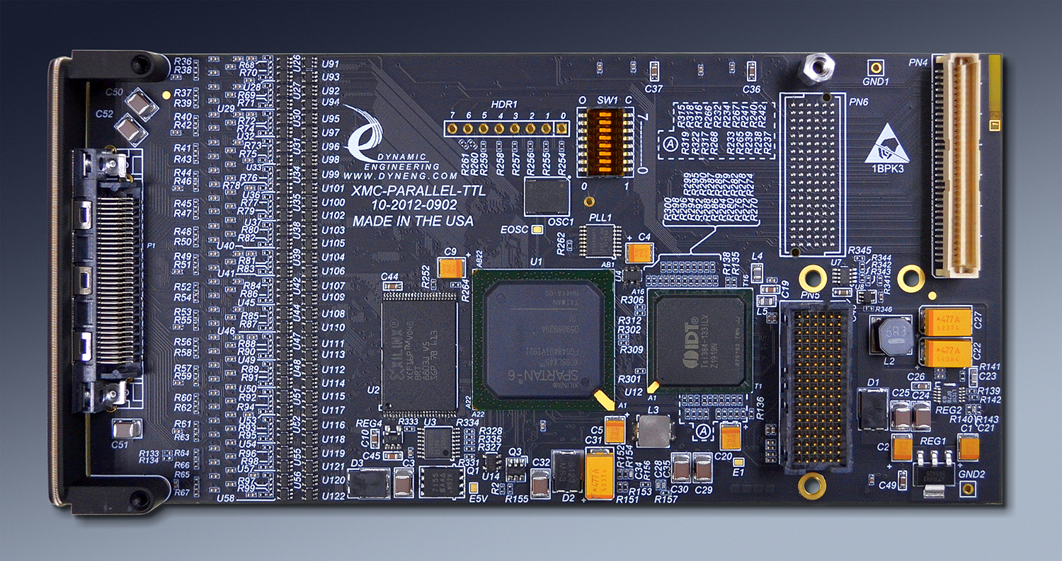
Does your system require single ended TTL or CMOS level signals? Dynamic Engineering has a multitude of solutions covering different architectures and mezzanine types. XMC-Parallel-TTL is based on the popular PMC-Parallel-TTL design. The IO definitions are the same to allow ease of migration from PMC to XMC when the time comes. XMC-Parallel-TTL retains Pn4 and Bezel IO options. The bus interface is a 4 lane PCIe implementation using the XMC connector as seen in the photo above. The FPGA is a Spartan VI [Rev02 and later]. The FPGA can be redefined to provide state-machines and other IO controllers for specific applications. We ported the "BA16" design to this board with a simple recompile to create the first implementation. XMC-Parallel-TTL is in use testing our XMC carriers using DMA and the IO connections.
XMC compatible XMC-Parallel-TTL has 64 independent digital IO. The high density makes efficient use of precious XMC slot resources. The IO is available for system connection both through the front panel and via the rear [Pn4, Pn6] connectors. A high density 68 pin VHDCI front panel connector provides the front panel IO. The rear panel IO has a PIM and PIM Carrier available for rear panel wiring options. HDEterm68 can be used as a breakout for the front or rear panel IO. HDEcabl68 provides a convenient cable. The pin definitions are consistent with the PMC Parallel IO card to enable users of PMC-Parallel-IO to migrate to the XMC-Parallel-TTL quickly and easily.
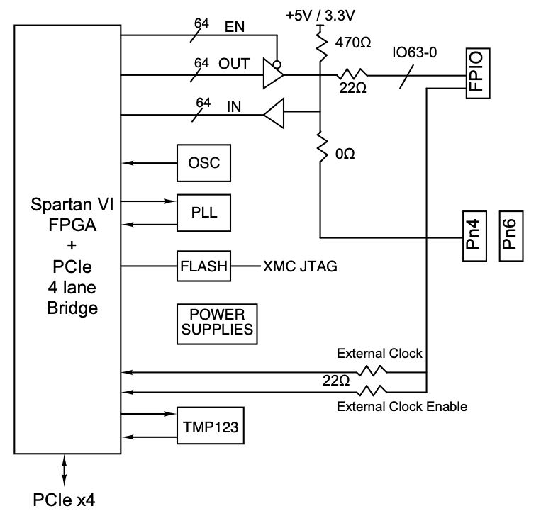
Each IO is independently programmable. The outputs can be enabled and driven high or low. When disabled on-board pull-ups terminate the lines. The pull-ups can be referenced to 5V or 3.3V with software. A master enable is available to allow the user to synchronize the upper and lower outputs for coherant 64 bit operation in a 32 bit system. The master enable can be set to allow independent upper and lower bank updates. The transmitters are ´125 buffers and the receivers are Schmidt triggered to provide hysterisis. The IO are isolated from the connectors to allow connector selection without creating "stubs". The isolation is in the form of 0402 packaged resistors. Typlically 0 ohms to the rear connector and 22 ohms to the front. Other values can be used. Similarly the pull-ups are individual packages and can be changed from the 470 ohm standard.
All channels can be read as inputs regardless of the transmit enable programming. Local loop-back can be used for BIT. All IO channels can be used as interrupt generators. Interrupts are programmable to be based on either or both edges for "Change of State" operation. An external clock, PCI clock, or oscillator can be selected for the reference on the COS operation. The reference can be programmed to be divided to create lower frequencies. A PLL is available to support user frequency selection to provide the right sampling rate for your application.
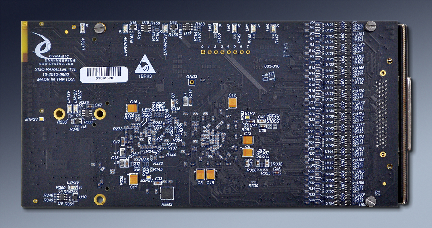
VPWR is used to create 5V using a buck-boost DC:DC converter. The Buck-Boost converter design allows XMC-Parallel-TTL to operate with VPWR defined to be 12V or 5V without user intervention. VPWR is monitored and LED´s indicate which power level is supplied. The LEDs are on the rear of the card for easy viewing.
LEDs indicate which PCIe lanes are in use. XMC-Parallel-TTL can operate with 1, 2, or 4 lanes.
The FPGA is loaded from FLASH allowing for field updates and custom designs. You can order based on a similar design and update to the exact design later allowing for a quick start. The FLASH is on-board reprogrammable using SW. Please see our reference application for an example.
Additional features include a user switch [8 positions] , PLL with 4 inputs to the FPGA, local oscillator, and temperature sensor. The reference to the PLL is sourced by the FPGA allowing for many references and programmed frequencies. A high quality industrial temperature 10 PPM device is installed with 50 MHz [standard] or a design specific frequency. The driver and reference software include utilities to load and reload the PLL with user specific frequency selections. The switch can be used to identify which XMC is being communicated with when more than one are installed in a system or for whatever options [SW or FPGA] are designed. The temperature sensor is read with software. Please see the reference SW to see how to read the temperature sensor and convert to centigrade.
All of the IO are routed through the FPGA device to allow for custom applications that require hardware intervention or specific timing. For example the design of the XMC-Parallel-TTL supports internal FIFOs and DMA. With an added state-machine for your interface the hardware can provide much more than a simple parallel interface. A partial list of functions includes: Manchester, Miller, SDLC, UART, Serial, Parallel, GPIO, COS, Custom, LADEE, NMS, Camera, Ternary, Low Speed, High Speed, Telemetry, Master & Target interactive IO, Adaptive. To support the functions the designs include: memory elements instantiated with FIFO, Dual Port RAM, register files, as well as state-machines, counters, timers, dividers, registers, CRC and Parity generation / checking, software drivers and applications, DMA [direct memory access] and the glue that goes with it. Our designs are all written in VHDL and done in a heirarchy allowing direct porting of different features to create new implementations. Contact Dynamic Engineering for client specific implementations.
The base model has a simple to use register based interface. The registers are mapped as 32 bit words. All registers are read-writeable. The Windows® compatible [Win10] driver is available to provide the system level interface for this design. Use standard C/C++ to control your hardware or use the Hardware manual to make your own software interface. The hardware manual is downloadable from the bottom of this page. The software manual is also available on-line.
Install into a PC with PCIe8LXMCX1 or PCIe8LXMCX2. Install into VPX with VPX8LXMC3U
A new custom version can be implemented in a very reasonable time. Typically a few weeks of design time for a medium sized project including the new VHDL set, Windows® or Linux or VxWorks driver, reference software package, and documentation. Examples of the designs performed to date are listed toward the bottom of this page and pages for previous versions. Check if the configuration you need already exists or if we need to work on a custom version for you. Our software engineers can provide the middleware to tie our kernel level implementation to your application.
We can be rapid with our response because the designs are structured to allow ports to be moved in and out to create new design sets. Most designs have a fairly large component of reused "known good" VHDL that we can pull from allowing us to focus on the new functions required for your implementation. You are getting the benefit of many man-years of design and test time with each new version created. Join our high reliability clients by taking advantage of our know-how to help speed your project to completion. email us your wish list or call today
XMCs are independently specificed through VITA for the form factor, connectors and pinouts of the PCIe signaling; you can use with any carrier from any vendor that supports standard XMC´s. To make it even easier Dynamic Engineering XMCs allow operation with VPWR set to 12 or 5V.
It all starts with the PCB [Printed Circuit Board]. Quality design and quality materials are required to meet the strenuous requirements of many of our implementations. You can do the job quickly or you can do the design correctly. We pride ourselves on taking the time to put the extra work into our layouts. The quality goes in before the parts go on. In addition to routing strategy and layer counts, Via size, plating requirements, break-out trace widths, and materials are areas where quality comes into play. The via size and method of trace attachment to the via affect the signal shape and reliability. Using tear-drop trace connections to pads, via´s and through hole components enhance the reliability and minimize the impedance discontinuity resulting in a cleaner signal. Using larger vias and traces provides adequate copper for proper power distribution and more surface area to bond to where traces are interconnected. The combination provides better vibration endurance than smaller vias and traces would provide. The design has several power planes with sufficient copper weight and coverage to provide the references required for the routing plus the current and voltages needed by the various devices on the board. The larger features make the design work more difficult since there is less room to "play with" and the end result is worth it. Since 1998 Dynamic Engineering designs have enjoyed an excellent track record for reliability.
The PCIe interface has a published set of requirements for compliance which restrict length, impedance, loading and other factors. XMC-Parallel-TTL is compliant with the PCIe Specification. The IO section has requirements based on the IO type and the purpose for the IO. A very conservative approach has been taken to allow operation with any client requirement. The design has matched length connections from the FPGA ball to the seating plane of the connector. The lengths are matched to the "mil". The Impedance is controlled and the signals routed with proper spacing to avoid cross talk etc. The other features including memory, PLL, oscillator, and power supplies are implemented within the PCB to exceed the operational requirements for those devices.
The IO is available through either the front panel mounted VHDCI connector or Pn4 and/or Pn6 or some combination. Each IO is isolated from the connectors with zero ohm resistors. The resistors are mounted front and rear and tied together at each IO to allow for a stub length of 1/16th in. The Connectors are routed from the resistors directly allowing for almost zero stub lengths and the option to connect front or rear IO options.
Clock options are frequently a major factor in embedded designs. Getting the right reference to the right part of the design and allowing for local control of exact frequencies. With a PLL providing 4 programmable outputs, reference oscillator, internal DCM´s and buffering plus programable dividers instantiated within the VHDL. The PLL can be programmed to "any" fixed frequency, the DCM used to create phase variations, and local dividers to allow on-the-fly channel based frequency changes.
"Channelized DMA"™ is an important feature of the XMC-Parallel-TTL design. With "Channelized DMA"™ you have a separate DMA engine for each transmitter and each receiver within each port. Each state-machine can be serviced independently with DMA without requiring intervention from the host. Large data transfers can happen between multiple connections while the CPU is off doing something else. In non-channelized designs the CPU will have to intervene each time a different port needs to be serviced. With a channelized approach the hardware takes care of the local arbitration, and eliminates the intervention for better system performance and less latency.
XMC compatible XMC-Parallel-TTL has 64 independent digital IO. The high density makes efficient use of precious XMC slot resources. The IO is available for system connection both through the front panel and via the rear [Pn4, Pn6] connectors. A high density 68 pin VHDCI front panel connector provides the front panel IO. The rear panel IO has a PIM and PIM Carrier available for rear panel wiring options. HDEterm68 can be used as a breakout for the front or rear panel IO. HDEcabl68 provides a convenient cable. The pin definitions are consistent with the PMC Parallel IO card to enable users of PMC-Parallel-IO to migrate to the XMC-Parallel-TTL quickly and easily.
Each IO is independently programmable. The outputs can be enabled and driven high or low. When disabled on-board pull-ups terminate the lines. The pull-ups can be referenced to 5V or 3.3V with software. A master enable is available to allow the user to synchronize the upper and lower outputs for coherant 64 bit operation in a 32 bit system. The master enable can be set to allow independent upper and lower bank updates. The transmitters are ´125 buffers and the receivers are Schmidt triggered to provide hysterisis. The IO are isolated from the connectors to allow connector selection without creating "stubs". The isolation is in the form of 0402 packaged resistors. Typlically 0 ohms to the rear connector and 22 ohms to the front. Other values can be used. Similarly the pull-ups are individual packages and can be changed from the 470 ohm standard.
All channels can be read as inputs regardless of the transmit enable programming. Local loop-back can be used for BIT. All IO channels can be used as interrupt generators. Interrupts are programmable to be based on either or both edges for "Change of State" operation. An external clock, PCI clock, or oscillator can be selected for the reference on the COS operation. The reference can be programmed to be divided to create lower frequencies. A PLL is available to support user frequency selection to provide the right sampling rate for your application.
VPWR is used to create 5V using a buck-boost DC:DC converter. The Buck-Boost converter design allows XMC-Parallel-TTL to operate with VPWR defined to be 12V or 5V without user intervention. VPWR is monitored and LED´s indicate which power level is supplied. The LEDs are on the rear of the card for easy viewing.
LEDs indicate which PCIe lanes are in use. XMC-Parallel-TTL can operate with 1, 2, or 4 lanes.
The FPGA is loaded from FLASH allowing for field updates and custom designs. You can order based on a similar design and update to the exact design later allowing for a quick start. The FLASH is on-board reprogrammable using SW. Please see our reference application for an example.
Additional features include a user switch [8 positions] , PLL with 4 inputs to the FPGA, local oscillator, and temperature sensor. The reference to the PLL is sourced by the FPGA allowing for many references and programmed frequencies. A high quality industrial temperature 10 PPM device is installed with 50 MHz [standard] or a design specific frequency. The driver and reference software include utilities to load and reload the PLL with user specific frequency selections. The switch can be used to identify which XMC is being communicated with when more than one are installed in a system or for whatever options [SW or FPGA] are designed. The temperature sensor is read with software. Please see the reference SW to see how to read the temperature sensor and convert to centigrade.
All of the IO are routed through the FPGA device to allow for custom applications that require hardware intervention or specific timing. For example the design of the XMC-Parallel-TTL supports internal FIFOs and DMA. With an added state-machine for your interface the hardware can provide much more than a simple parallel interface. A partial list of functions includes: Manchester, Miller, SDLC, UART, Serial, Parallel, GPIO, COS, Custom, LADEE, NMS, Camera, Ternary, Low Speed, High Speed, Telemetry, Master & Target interactive IO, Adaptive. To support the functions the designs include: memory elements instantiated with FIFO, Dual Port RAM, register files, as well as state-machines, counters, timers, dividers, registers, CRC and Parity generation / checking, software drivers and applications, DMA [direct memory access] and the glue that goes with it. Our designs are all written in VHDL and done in a heirarchy allowing direct porting of different features to create new implementations. Contact Dynamic Engineering for client specific implementations.
The base model has a simple to use register based interface. The registers are mapped as 32 bit words. All registers are read-writeable. The Windows® compatible [Win10] driver is available to provide the system level interface for this design. Use standard C/C++ to control your hardware or use the Hardware manual to make your own software interface. The hardware manual is downloadable from the bottom of this page. The software manual is also available on-line.
Install into a PC with PCIe8LXMCX1 or PCIe8LXMCX2. Install into VPX with VPX8LXMC3U
A new custom version can be implemented in a very reasonable time. Typically a few weeks of design time for a medium sized project including the new VHDL set, Windows® or Linux or VxWorks driver, reference software package, and documentation. Examples of the designs performed to date are listed toward the bottom of this page and pages for previous versions. Check if the configuration you need already exists or if we need to work on a custom version for you. Our software engineers can provide the middleware to tie our kernel level implementation to your application.
We can be rapid with our response because the designs are structured to allow ports to be moved in and out to create new design sets. Most designs have a fairly large component of reused "known good" VHDL that we can pull from allowing us to focus on the new functions required for your implementation. You are getting the benefit of many man-years of design and test time with each new version created. Join our high reliability clients by taking advantage of our know-how to help speed your project to completion. email us your wish list or call today
XMCs are independently specificed through VITA for the form factor, connectors and pinouts of the PCIe signaling; you can use with any carrier from any vendor that supports standard XMC´s. To make it even easier Dynamic Engineering XMCs allow operation with VPWR set to 12 or 5V.
It all starts with the PCB [Printed Circuit Board]. Quality design and quality materials are required to meet the strenuous requirements of many of our implementations. You can do the job quickly or you can do the design correctly. We pride ourselves on taking the time to put the extra work into our layouts. The quality goes in before the parts go on. In addition to routing strategy and layer counts, Via size, plating requirements, break-out trace widths, and materials are areas where quality comes into play. The via size and method of trace attachment to the via affect the signal shape and reliability. Using tear-drop trace connections to pads, via´s and through hole components enhance the reliability and minimize the impedance discontinuity resulting in a cleaner signal. Using larger vias and traces provides adequate copper for proper power distribution and more surface area to bond to where traces are interconnected. The combination provides better vibration endurance than smaller vias and traces would provide. The design has several power planes with sufficient copper weight and coverage to provide the references required for the routing plus the current and voltages needed by the various devices on the board. The larger features make the design work more difficult since there is less room to "play with" and the end result is worth it. Since 1998 Dynamic Engineering designs have enjoyed an excellent track record for reliability.
The PCIe interface has a published set of requirements for compliance which restrict length, impedance, loading and other factors. XMC-Parallel-TTL is compliant with the PCIe Specification. The IO section has requirements based on the IO type and the purpose for the IO. A very conservative approach has been taken to allow operation with any client requirement. The design has matched length connections from the FPGA ball to the seating plane of the connector. The lengths are matched to the "mil". The Impedance is controlled and the signals routed with proper spacing to avoid cross talk etc. The other features including memory, PLL, oscillator, and power supplies are implemented within the PCB to exceed the operational requirements for those devices.
The IO is available through either the front panel mounted VHDCI connector or Pn4 and/or Pn6 or some combination. Each IO is isolated from the connectors with zero ohm resistors. The resistors are mounted front and rear and tied together at each IO to allow for a stub length of 1/16th in. The Connectors are routed from the resistors directly allowing for almost zero stub lengths and the option to connect front or rear IO options.
Clock options are frequently a major factor in embedded designs. Getting the right reference to the right part of the design and allowing for local control of exact frequencies. With a PLL providing 4 programmable outputs, reference oscillator, internal DCM´s and buffering plus programable dividers instantiated within the VHDL. The PLL can be programmed to "any" fixed frequency, the DCM used to create phase variations, and local dividers to allow on-the-fly channel based frequency changes.
"Channelized DMA"™ is an important feature of the XMC-Parallel-TTL design. With "Channelized DMA"™ you have a separate DMA engine for each transmitter and each receiver within each port. Each state-machine can be serviced independently with DMA without requiring intervention from the host. Large data transfers can happen between multiple connections while the CPU is off doing something else. In non-channelized designs the CPU will have to intervene each time a different port needs to be serviced. With a channelized approach the hardware takes care of the local arbitration, and eliminates the intervention for better system performance and less latency.
XMC-Parallel-TTL Features
Size
Std XMC 74mm x 149mm nominal. Low profile components on rear
IO
64 independent IO. The pull-ups can be referenced to 3.3V or 5V via SW. Front Panel [Bezel], Rear IO [Pn4/Pn6] or Both ports available. Unused ports isolated with resistors for "zero bus stub". Matched IO within 1/1000 inch for on-board traces to front and rear.
Clocks
50 MHz PCI, 50 MHz oscillator ( other frequencies available), 4 programmable PLL inputs, Counters / Dividers / DCM for local clock control.
Interface Types
Custom programmed interfaces are available. Please send us a timing diagram, and we can program one for you. Most interfaces can be adapted from our large library of designs within a few weeks including the updated VHDL, Windows or Linux or VxWorks Driver, reference manuals etc. We can support on-site [ours] integration to help you get your application level software working. We can provide middleware to tie your application to our kernel level interface.
Alternatively choose one of the already completed versions and purchase off-the-shelf. Common requested and implemented interface types include: Manchester, Miller, SDLC, UART, Serial, Parallel, GPIO, COS, Custom, LADEE, NMS, Camera, Ternary, Low Speed, High Speed, Telemetry, Master & Target interactive IO, Adaptive. Mix and Match. Just like but different...
Alternatively choose one of the already completed versions and purchase off-the-shelf. Common requested and implemented interface types include: Manchester, Miller, SDLC, UART, Serial, Parallel, GPIO, COS, Custom, LADEE, NMS, Camera, Ternary, Low Speed, High Speed, Telemetry, Master & Target interactive IO, Adaptive. Mix and Match. Just like but different...
Pull-up Resistor
470 standard
Software Interface
Control registers are read-writeable
Windows®, Linux, reference SW and Drivers
Windows®, Linux, reference SW and Drivers
Interrupts
Software programmable interrupts on status, errors, completion of transfer, DMA, FIFO levels, custom events. Status can be polled for non-interrupt driven operation as well. All IO Channels can be programmed to cause interrupts. Each IO is programmable to be masked, rising, falling, both [COS].
Power Requirement
XMC standard. VPWR can be +5 or +12V. Linear and DC:DC power supplies for efficient power conversion.
Protection
The isolation resistor standard is 0 ohms to Pn4/Pn6 and 22 ohms to Bezel. Resistive coupling for current limiting and ESD protection
COS Clock
Input registers are programmable to capture data with the COS clk. SW can select PCI, external or Oscillator as the source for clock. A programmable divider [12 bit] allows a wide range of sampling frequencies to be selected. Some versions use the PLL for the COS clock definition.
Reliability
TBD million hours. Bellcore. GB 25c
XMC-Parallel-TTL Benefits
Speed
XMC-Parallel-TTL is a software controlled HW interface. As fast as the PCIe/PCI interface can push the data across, the outputs can change. Your time to market will be shortened by the easy to use interface, flexibility in design, and off-the-shelf availability. With DMA enabled and FIFO´s instantiated faster transfers can occur.
Price
XMC-Parallel-TTL has an attractive price, and low integration cost for a low system cost.
Ease of Use
XMC-Parallel-TTL is designed to be easy to use. Direct access to all features, aligned registers for larger access types, programmable features to allow personalization for your system. Please download the manuals and see for yourself. Reference software is provided in source form to get you started.
Availability
XMC-Parallel-TTL is a stocked design. A quick "PCO" to reflash and retest into your configuration when ordering an existing version. New NRE required designs will have some delay to implement, integrate and test.
XMC Specification Compatibility
XMC-Parallel-TTL is compliant per the VITA XMC specifications. Tested with PCIe based carriers. All Dynamic Engineering XMC Modules are compatible with PCIe8LXMCX1, PCIe8lXMCX2, VPX8LXMC3U , and XMC-UNIV-TEST. XMC-Parallel-TTL will operate with any XMC specification compliant carrier board.
Part Number: XMC-Parallel-TTL
Ordering Options
- XMC-Parallel-TTL Standard board - with SW selected 3.3/5 referenced Front Panel [Bezel] IO, 64 IO, Industrial Temperature components, Temperature Sensor
- -RP Switch to Pn4 IO
- -XIO Pn4 and Pn6 installed
- -XIOexc Pn6 only
- -ROHS Use ROHS processing. Standard processing is ""leaded"
- -CC Option to add Conformal Coating
- -12MM Option to switch from 10 mm spacing to 12MM.
XMC-Parallel-TTL Drivers
Software Support for XMC-Parallel-TTL-XXX includes: Windows® 10, and Linux compliant drivers
Please see the Driver manuals for the specifics of each type.
Drivers and Reference SW are developed for each type / version of XMC-Parallel-TTL implemented. When custom versions are ordered the NRE will include providing Windows, Linux, and or VxWorks packages. For off-the-shelf models, select on the models tab, the Windows® and Linux SW shown is included with your purchase of the HW. A small one-time charge is required for the VxWorks versions. Unsupported SW versions may have an NRE requirement.
Integration support is available. Please contact Dynamic Engineering for this option or download the Technical Support Description from the Company button.
XMC-Parallel-TTL Models
GPIO 64 TTL IO in a General Purpose IO configuration
Change of State [COS] with independent Rising and Falling selections to allow for data capture on either, neither, or both edges. Edge or Level selection to allow treating IO as level based. Separate interrupt enables for each IO. Independent polarity selection. Multiple programmable COS rates based on programmable PLL and local oscillator [16 bit divisor]. Dip Switch for user purposes. Temperature sensor. VHDCI and/or Rear connector options. Synchronization for upper and lower words can be used to control all 64 bits together or disabled for 2 32 bit ports. All bits can be read-back. Programmable Tx bits. Programmable IO reference [5V or 3.3V]. Design supports internal loop-back. Unified driver supports PMC and XMC models.
DMA support with 8Kx32 FIFO for user purposes.
Driver has utilities for programming the PLL using the "JED" file, reading the temperature, and managing all of the features.
Download the Parallel-TTL-GPIO Win10 Driver Package Manual
Download the Parallel-TTL-GPIO Linux Driver Package Manual
Download the Parallel-TTL-GPIO HW Manual