Made in USA
The Embedded Solutions Experts
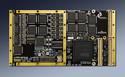
ccPMC-HOTLink
PMC Module with 6 ports HOTLink, plus secondary support bus [RS485, LVDS, TTL]


ccPMC-HOTLink Description
- Driver included with purchase
- Conduction Cooled PMC module
- 32/33 with DMA operation
- 6 HOTLink ports, 12 differential IO.
- Industrial Temperature parts standard
- Spartan 6 FPGA with BRAM for FIFO or RAM implementation
- PLL with 4 clock references
- 1 year warranty standard. Extended warranty available.
- ROHS and Standard processing available
HOTLink is used in applications demanding high speed and high reliability including sonar, radar, other scanning applications, seismic, oil exploration etc. Alternate purposes would include high speed buses between equipment or within equipment for command and control, data transfer etc. ccPMC-HOTLink is a conduction cooled PMC card with 6 HOTLink receiver/transmitter pairs plus 12 differential IO. Each of the HOTLink channels is supported with a separate DMA transfer engine plus local memory.
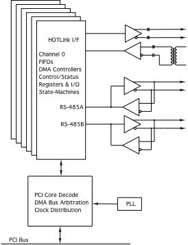
The HOTLink protocol implemented provides positive emitter coupled logic (PECL) data inputs and outputs. The receive side can be direct or transformer coupled. The transmit byte rate is determined by the programmed frequency of the PLL clock A output. This clock is multiplied ten times by the HOTLink transmitter to send the transmit byte data stream which is expanded to 10 bits by the internal 8B/10B encoder. The PLL is programmed via software over a serial I2C interface.
Up to six independent HOTLink channels are provided. Each HOTLink channel has four differential I/O signal pairs: A HOTLink differential PECL output, a HOTLink differential PECL input and two bi-directional differential RS-485 lines. The RS-485 IO each have independent direction and termination controls to allow programmable operation with many IO requirements. The 485 IO can be used for an alternate purpose and is directly controlled by the FPGA
The HOTLink input can be transformer-coupled into a dual 50Ω terminations referenced to 1.8 volts. The signals are then AC-coupled into the HOTLink receiver inputs. The HOTLink output is AC-coupled after the bias/termination network. Both AC coupling stages can be replaced for a DC coupled system.
ccPMC-HOTLink features a Spartan 6 FPGA. The FPGA allows for a lot of internal memory and more complex data manipulation in HW. The memory is typically used for FIFOs or RAM. The FIFOs can be accessed by single-word and DMA burst transfers. A FIFO test bit in each channel control register enables the data to be routed between the transmit and receive FIFOs for a full 32-bit path. The ports are supported with 12 independent DMA engines. Local arbitration keeps the data moving efficiently. DMA transfers can be programmed for any size transfer from very small to multiple megabytes using the scatter gather capable programming model.
This PMC module is conduction-cooled and has no front panel connector. All I/O connections are routed through PN4. All parts are industrial temp or better [-40C <=> +85C]. Conformal coating, thermal gluing and thermal foam are available options help adapt to your environment.
ccPMC-HOTLink Block Diagram
PMC Modules require a "carrier" in most cases to adapt them to the system. Dynamic Engineering has carrier solutions for a variety of formats.
PCIe implementations can be done with the PCIeBPMCX1 and PCIeBPMCX2.
PCI implementations can be done with the PCI2PMC and PCIBPMCX2.
cPCI 3U is supported with the cPCIBPMC3U64
cPCI 6U is supported with the cPCIBPMC6U.
PCI-104 is supported with the PCI104p2PMC.
PMC´s are independently specificed through VITA for the form factor, connectors and pinouts of the PCI signaling; you can use with any carrier from any vendor that supports standard PMCs. To make it even easier Dynamic Engineering PMCs feature a universal voltage PCI design to allow operation with VIO set to 3.3 or 5V.
It all starts with the PCB [Printed Circuit Board]. Quality design and quality materials are required to meet the strenuous requirements of many of our implementations. You can do the job quickly or you can do the design correctly. We pride ourselves on taking the time to put the extra work into our layouts. The quality goes in before the parts go on. In addition to routing strategy and layer counts, Via size, plating requirements, break-out trace widths, and materials are areas where quality comes into play. The via size and method of trace attachment to the via affect the signal shape and reliability. Using tear-drop trace connections to pads, via´s and through hole components enhance the reliability and minimize the impedance discontinuity resulting in a cleaner signal. The combination provides better vibration endurance than smaller vias and traces would provide. The design has several power planes with sufficient copper weight and coverage to provide the references required for the routing plus the current and voltages needed by the various devices on the board. The larger features make the design work more difficult since there is less room to "play with" and the end result is worth it. Since 1998 Dynamic Engineering designs have enjoyed an excellent track record for reliability.
The PCI interface has a published set of requirements for compliance which restrict length, impedance, loading and other factors. ccPMC-HOTLink is compliant with the PCI Specification. The IO section has requirements based on the IO type and the purpose for the IO. A very conservative approach has been taken to allow operation with any client requirement. The design has matched length connections from the FPGA ball to the seating plane of the connector. The lengths are matched to the "mil". The Impedance is controlled and the signals routed with proper spacing to avoid cross talk etc. The other features including memory, PLL, oscillator, and power supplies are implemented within the PCB to exceed the operational requirements for those devices.
Clock options are frequently a major factor in embedded designs. Getting the right reference to the right part of the design and allowing for local control of exact frequencies. With a PLL providing 4 programmable outputs, reference oscillator, internal DCMs and buffering plus programable dividers instantiated within the VHDL. The PLL can be programmed to "any" fixed frequency, the DCM used to create phase variations, and local dividers to allow on-the-fly channel based frequency changes.
"Channelized DMA"™ is an important feature of the ccPMC-HOTLink design. With "Channelized DMA"™ you have a separate DMA engine for each transmitter and each receiver within each port. Each state-machine can be serviced independently with DMA without requiring intervention from the host. Large data transfers can happen between multiple connections while the CPU is off doing something else. In non-channelized designs the CPU will have to intervene each time a different port needs to be serviced. With a channelized approach the hardware takes care of the local arbitration, and eliminates the intervention for better system performance and less latency.
The HOTLink protocol implemented provides positive emitter coupled logic (PECL) data inputs and outputs. The receive side can be direct or transformer coupled. The transmit byte rate is determined by the programmed frequency of the PLL clock A output. This clock is multiplied ten times by the HOTLink transmitter to send the transmit byte data stream which is expanded to 10 bits by the internal 8B/10B encoder. The PLL is programmed via software over a serial I2C interface.
Up to six independent HOTLink channels are provided. Each HOTLink channel has four differential I/O signal pairs: A HOTLink differential PECL output, a HOTLink differential PECL input and two bi-directional differential RS-485 lines. The RS-485 IO each have independent direction and termination controls to allow programmable operation with many IO requirements. The 485 IO can be used for an alternate purpose and is directly controlled by the FPGA
The HOTLink input can be transformer-coupled into a dual 50Ω terminations referenced to 1.8 volts. The signals are then AC-coupled into the HOTLink receiver inputs. The HOTLink output is AC-coupled after the bias/termination network. Both AC coupling stages can be replaced for a DC coupled system.
ccPMC-HOTLink features a Spartan 6 FPGA. The FPGA allows for a lot of internal memory and more complex data manipulation in HW. The memory is typically used for FIFOs or RAM. The FIFOs can be accessed by single-word and DMA burst transfers. A FIFO test bit in each channel control register enables the data to be routed between the transmit and receive FIFOs for a full 32-bit path. The ports are supported with 12 independent DMA engines. Local arbitration keeps the data moving efficiently. DMA transfers can be programmed for any size transfer from very small to multiple megabytes using the scatter gather capable programming model.
This PMC module is conduction-cooled and has no front panel connector. All I/O connections are routed through PN4. All parts are industrial temp or better [-40C <=> +85C]. Conformal coating, thermal gluing and thermal foam are available options help adapt to your environment.
PCIe implementations can be done with the PCIeBPMCX1 and PCIeBPMCX2.
PCI implementations can be done with the PCI2PMC and PCIBPMCX2.
cPCI 3U is supported with the cPCIBPMC3U64
cPCI 6U is supported with the cPCIBPMC6U.
PCI-104 is supported with the PCI104p2PMC.
PMC´s are independently specificed through VITA for the form factor, connectors and pinouts of the PCI signaling; you can use with any carrier from any vendor that supports standard PMCs. To make it even easier Dynamic Engineering PMCs feature a universal voltage PCI design to allow operation with VIO set to 3.3 or 5V.
It all starts with the PCB [Printed Circuit Board]. Quality design and quality materials are required to meet the strenuous requirements of many of our implementations. You can do the job quickly or you can do the design correctly. We pride ourselves on taking the time to put the extra work into our layouts. The quality goes in before the parts go on. In addition to routing strategy and layer counts, Via size, plating requirements, break-out trace widths, and materials are areas where quality comes into play. The via size and method of trace attachment to the via affect the signal shape and reliability. Using tear-drop trace connections to pads, via´s and through hole components enhance the reliability and minimize the impedance discontinuity resulting in a cleaner signal. The combination provides better vibration endurance than smaller vias and traces would provide. The design has several power planes with sufficient copper weight and coverage to provide the references required for the routing plus the current and voltages needed by the various devices on the board. The larger features make the design work more difficult since there is less room to "play with" and the end result is worth it. Since 1998 Dynamic Engineering designs have enjoyed an excellent track record for reliability.
The PCI interface has a published set of requirements for compliance which restrict length, impedance, loading and other factors. ccPMC-HOTLink is compliant with the PCI Specification. The IO section has requirements based on the IO type and the purpose for the IO. A very conservative approach has been taken to allow operation with any client requirement. The design has matched length connections from the FPGA ball to the seating plane of the connector. The lengths are matched to the "mil". The Impedance is controlled and the signals routed with proper spacing to avoid cross talk etc. The other features including memory, PLL, oscillator, and power supplies are implemented within the PCB to exceed the operational requirements for those devices.
Clock options are frequently a major factor in embedded designs. Getting the right reference to the right part of the design and allowing for local control of exact frequencies. With a PLL providing 4 programmable outputs, reference oscillator, internal DCMs and buffering plus programable dividers instantiated within the VHDL. The PLL can be programmed to "any" fixed frequency, the DCM used to create phase variations, and local dividers to allow on-the-fly channel based frequency changes.
"Channelized DMA"™ is an important feature of the ccPMC-HOTLink design. With "Channelized DMA"™ you have a separate DMA engine for each transmitter and each receiver within each port. Each state-machine can be serviced independently with DMA without requiring intervention from the host. Large data transfers can happen between multiple connections while the CPU is off doing something else. In non-channelized designs the CPU will have to intervene each time a different port needs to be serviced. With a channelized approach the hardware takes care of the local arbitration, and eliminates the intervention for better system performance and less latency.
ccPMC-HOTLink Features
Size
Conduction Cooled PMC Standard dimensions 74mm x 143.75mm nominal. Low profile components on rear
HOTLink Interface
6 independent Bidirectional PECL based HOTLink channels. Impedance controlled differentially routed channels.
Clocks
33 MHz PCI, 50 MHz oscillator ( other frequencies available), 4 programmable PLL inputs, Counters / Dividers / DCM for local clock control.
RS485/LVDS Interface
6 pairs of RS485/LVDS IO can be allocated 2 per HOTLink channel or used as a separate function with 12 available. 40/200 MHz IO, matched length, differentially routed with controlled impedance. Programmable terminations and options for tristate [pull-up/pulldown] control.
Cable interface
Pn4 backplane connection. Your PMC carrier will specify the system connector.
Software Interface
Control registers are read-writeable
Windows®, Linux, VxWorks reference SW and Drivers
Windows®, Linux, VxWorks reference SW and Drivers
Interrupts
Software programmable interrupts on status, errors, completion of transfer, DMA, FIFO levels, custom events. Status can be polled for non-interrupt driven operation as well.
Power Requirement
+5V, 3.3V plus 2.5, 1.8, 1.2 with local DC:DC power supplies for efficient power conversion.
Custom
All bits are routed through the FPGA to allow for custom state-machine implementations. FIFO and Dual Port RAM can be implemented.
Statement of Volatility
Reliability
TBD million hours. Bellcore. GB 25c
ccPMC-HOTLink Benefits
Speed
Your time to market will be shortened by the easy to use interface, flexibility in design, and off-the-shelf availability. ccPMC-HOTLink is a software controlled HW interface. With DMA enabled and FIFOs instantiated, fast transfers can occur. Each channel has a separate DMA controller to allow for high speed large transfers without SW intervention required.
Price
ccPMC-HOTLink has an attractive price, and low integration cost for a low system cost. ccPMC-HOTLink can be used with the PIM Universal and PIM Carrier in cPCI environments. An integrated rear IO transition solution with your specific connector requirements can be designed for you. Please contact Dynamic Engineering about your IO requirements.
Ease of Use
PMC- Parallel - TTL is designed to be easy to use. Direct access to all features, aligned registers for larger access types, programmable features to allow personalization for your system. Please download the manuals and see for yourself. Reference software is provided in source form to get you started.
Availability
ccPMC-HOTLink iis designed to be easy to program and use. Direct access to all registers, LW aligned programming Driver and reference SW available. Please download the manuals and see for yourself. The drivers [Windows® or Linux] come with reference software demonstrating DMA, register and memory accesses, PLL programming utilities and loop-back tests. The reference software is in source form and can be used for your design. Modify away.
PMC Specification Compatibility
ccPMC-HOTLink is compliant per the VITA PMC/CMC specifications. ccPMC-HOTLink is also compliant with the conduction cooled PMC specification. Tested with PCI and PCIe based carriers. All Dynamic Engineering PMC Modules are compatible with the PCIeBPMCX1, ccPMC-HOTLink will operate with any PMC specification compliant carrier board.
Part Number: ccPMC-HOTLink
Ordering Options
- ccPMC-HOTLink Standard board - full port compliment, PECL, 485 IO
- -ROHS Use ROHS processing. Standard processing is ""leaded"
- -CC Option to add Conformal Coating
- -XXX Replace XXX with model number from Models tab
ccPMC-HOTLink Drivers
Software Support for ccPMC-HOTLink-XXX includes: Windows, and Linux compliant drivers. VxWorks by special request.
Please see the Driver manuals for the specifics of each type.
Drivers and Reference SW are developed for each type / version of ccPMC-HOTLink implemented. When custom versions are ordered the NRE will include providing Windows, Linux, and or VxWorks packages. For off-the-shelf models, select on the models tab, the Windows® and Linux SW shown is included with your purchase of the HW. A one-time charge is required for the VxWorks versions. Unsupported SW versions may have an NRE requirement.
Integration support is available. Please contact Dynamic Engineering for this option or download the Technical Support Description from the Company button.
ccPMC-HOTLink Models
Description: AP1 is a single channel receive oriented Image capture design. 64Kx32 FIFO´s for receive and transmit. K chars are used to pad with nulls, provide a synchronization pattern to initiate frame capture and to provide the interframe gap. A PLL with SW interface provides frequency programability. Options for interrupt and polled operation with individual masks to allow for a variety of operational concepts. Windows® 7 driver and UserAp available.
Download the ccPMC-HOTLink AP1 Rev C Hardware Manual
Kaon1: TTL and HOTLink interfaces with command / response type interaction. 2 Ports per ccPMC-HOTLink-KAON1. Windows® and Linux [debian] support. AC Couple TTL interfaces. TTL In used to trigger HOTLink [PECL] out.
Download the ccPMC-HOTLink KAON1 HW Manual
Download the ccPMC-HOTLink KAON1 Linux Manual
Download the ccPMC-HOTLink KAON1 Windows 10 Manual
ccPMC-HOTLink previous PCB models requiring port to current PCB/FPGA
Description: The rev 1 design HOTLink receiver is supported by a 4k by 32-bit input data FIFO and the HOTLink transmitter has a 2k by 32-bit output data FIFO. These FIFO´s can be accessed by single-word read/writes as well as DMA burst transfers. A FIFO test bit in each channel control register enables the data to be routed from the transmit to the receive FIFO for a full 32-bit path for loop-back testing of the FIFO´s. Data is latched and the bus immediately released on a write-cycle. As soon as data is present in the FIFO it is pre-read to be immediately available for a read cycle. This allows minimal delay on the PCI write to transmit FIFO path and PCI read from the receive FIFO path as well as the accesses for the transmit and receive state machines.
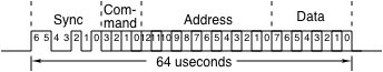 Base Transmit Request Timing
Each channel also has two bi-directional RS-485 lines running an asynchronous 32-bit msb first protocol with low marking state. The 16x receive clock is supplied by the PLL clock A output. Each line is supported by a 1k by 32-bit FIFO that can be configured for either input or output use. Either line can be configured as a general purpose input or output, or setup to send data access requests at regular intervals (variable from 1.5 msec to about 3.5 msec in 2 usec increments) using a pre-defined 7-bit sync pattern. These requests trigger the output of a block of data that is received by the HOTLink receiver. The RS-485 FIFO´s are only accessed using single-word transfers. Each FIFO can be directly written and read for FIFO testing or normal operation as either a receiver or transmitter.
Each channel also has two bi-directional RS-485 lines running an asynchronous 32-bit msb first protocol with low marking state. The 16x receive clock is supplied by the PLL clock A output. Each line is supported by a 1k by 32-bit FIFO that can be configured for either input or output use. Either line can be configured as a general purpose input or output, or setup to send data access requests at regular intervals (variable from 1.5 msec to about 3.5 msec in 2 usec increments) using a pre-defined 7-bit sync pattern. These requests trigger the output of a block of data that is received by the HOTLink receiver. The RS-485 FIFO´s are only accessed using single-word transfers. Each FIFO can be directly written and read for FIFO testing or normal operation as either a receiver or transmitter. Download the ccPMC-HOTLink Rev A Hardware Manual
Download the ccPMC-HOTLink Rev A Windows® Driver Manual
Download the ccPMC-HOTLink Rev A Linux Driver Manual
Download the ccPMC-HOTLink AP1 Rev C Hardware Manual
Kaon1: TTL and HOTLink interfaces with command / response type interaction. 2 Ports per ccPMC-HOTLink-KAON1. Windows® and Linux [debian] support. AC Couple TTL interfaces. TTL In used to trigger HOTLink [PECL] out.
Download the ccPMC-HOTLink KAON1 HW Manual
Download the ccPMC-HOTLink KAON1 Linux Manual
Download the ccPMC-HOTLink KAON1 Windows 10 Manual
ccPMC-HOTLink previous PCB models requiring port to current PCB/FPGA
Description: The rev 1 design HOTLink receiver is supported by a 4k by 32-bit input data FIFO and the HOTLink transmitter has a 2k by 32-bit output data FIFO. These FIFO´s can be accessed by single-word read/writes as well as DMA burst transfers. A FIFO test bit in each channel control register enables the data to be routed from the transmit to the receive FIFO for a full 32-bit path for loop-back testing of the FIFO´s. Data is latched and the bus immediately released on a write-cycle. As soon as data is present in the FIFO it is pre-read to be immediately available for a read cycle. This allows minimal delay on the PCI write to transmit FIFO path and PCI read from the receive FIFO path as well as the accesses for the transmit and receive state machines.
Base Transmit Request TimingEach channel also has two bi-directional RS-485 lines running an asynchronous 32-bit msb first protocol with low marking state. The 16x receive clock is supplied by the PLL clock A output. Each line is supported by a 1k by 32-bit FIFO that can be configured for either input or output use. Either line can be configured as a general purpose input or output, or setup to send data access requests at regular intervals (variable from 1.5 msec to about 3.5 msec in 2 usec increments) using a pre-defined 7-bit sync pattern. These requests trigger the output of a block of data that is received by the HOTLink receiver. The RS-485 FIFO´s are only accessed using single-word transfers. Each FIFO can be directly written and read for FIFO testing or normal operation as either a receiver or transmitter.
Each channel also has two bi-directional RS-485 lines running an asynchronous 32-bit msb first protocol with low marking state. The 16x receive clock is supplied by the PLL clock A output. Each line is supported by a 1k by 32-bit FIFO that can be configured for either input or output use. Either line can be configured as a general purpose input or output, or setup to send data access requests at regular intervals (variable from 1.5 msec to about 3.5 msec in 2 usec increments) using a pre-defined 7-bit sync pattern. These requests trigger the output of a block of data that is received by the HOTLink receiver. The RS-485 FIFO´s are only accessed using single-word transfers. Each FIFO can be directly written and read for FIFO testing or normal operation as either a receiver or transmitter. Download the ccPMC-HOTLink Rev A Hardware Manual
Download the ccPMC-HOTLink Rev A Windows® Driver Manual
Download the ccPMC-HOTLink Rev A Linux Driver Manual