Made in USA
The Embedded Solutions Experts
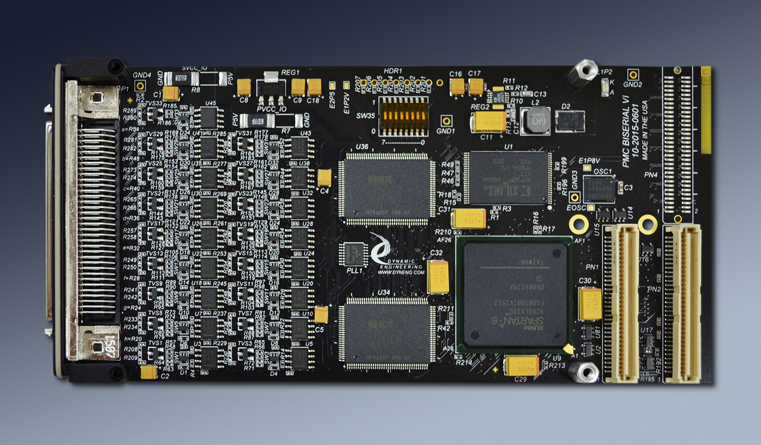
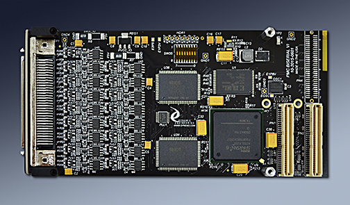
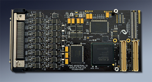
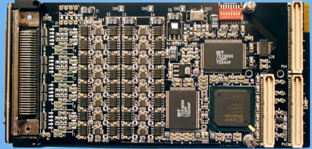
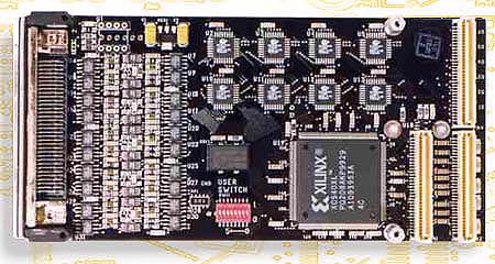
PMC-BiSerial-VI
PMC Module with Spartan 6 FPGA, PLL, 32/34 Independent Differential IO - RS422, RS-485, LVDS
Order This Item

PMC-BiSerial-VI Description
- Windows, Linux,
- Standard PMC module
- 32/33 with DMA operation
- 34/32 independent differential IO. Each with programmable termination and direction.
- RS-485, RS-422, LVDS and mixed
- Bezel and/or rear IO
- 256 Mbytes DDR with Clock Locked indicator - new with Rev 7
- Spartan 6 FPGA with BRAM for FIFO or RAM implementation
- PLL with 4 clock references
- 1 year warranty standard. Extended warranty available.
- Extended [Industrial] Temperature standard. -40C ⇔ +85C
- ROHS and Standard processing available
25 years of PMC BiSerial models and counting. PMC-BiSerial-VI includes a Spartan 6 [Xilinx], DDR, PLL, Differential IO [LVDS or RS-485 or mixed], programmable terminations, DMA and build options for front or rear IO. PMC-BiSerial-VI incorporates industrial temperature or better components. The block RAM within the 100 size Spartan VI provides enough internal RAM for many designs. The DDR expands that memory for systems where large amounts of storage are required. Building on the knowledge and experience gathered from multiple IP and PMC BiSerial implementations and adding in the latest technology has created Revision 7 of PMC-BiSerial-VI. The latest updates include replacing the previous model external FIFOs with DDR for a massive upgrade in storage, upgrading the termination switches, and adding temperature measurement.
The 34 IO can be configured to support one function, one function replicated several times, or multiple functions. For example: "UART" has 8 UART channels, while the "ORB2" has 8 channels with 4 different functions. A real space saver when you need to have some Manchester to go with your UART and HDLC ports. A partial list of functions implemented in "Channels" includes: Manchester, Miller, SDLC, HDLC, UART, Serial, Parallel, GPIO, COS, Custom, LADEE, NMS, Camera, Ternary, Low Speed, High Speed, Telemetry, Master & Target interactive IO, Adaptive. To support the functions the designs include: memory elements instantiated with FIFO, Dual Port RAM, register files, as well as state-machines, counters, timers, dividers, registers, CRC and Parity generation/checking, software drivers and applications, DMA [direct memory access] and the glue that goes with it. Our designs are all written in VHDL and done in a heirarchy allowing direct porting of different features to create new implementations.
More than 50 customerized versions of the BiSerial family and counting. IP-BiSerial-VI, PMC-BiSerial-VI, PC104p-BiSerial-VI, PCIe-BiSerialDb37, and PMC-BiSerial-6T20 are recommended for new designs.
The hardware has been used to interface with a wide variety of equipment. What do you need to communicate with? Control? Capture data from? Please see the tabs for current and previous portable BiSerial implementations. Descriptions and manuals available. We have been doing custom versions of the BiSerial since 1998 when the IP version was released.
A new custom version can be implemented in a very reasonable time. Typically 2-3 weeks of design time for a medium sized project including the new VHDL set, Windows® or Linux driver, reference software package, and documentation. Examples of the designs performed to date are listed . Please use the tabs to see the current and previous versions of BiSerial.
We can be rapid with our response because the designs are structured to allow channels to be moved in and out to create new design sets. Most designs have a fairly large component of reused "known good" VHDL that we can pull from allowing us to focus on the new functions required for your implementation. You are getting the benefit of many man-years of design and test time with each new version created. Join our high reliability clients by taking advantage of our know-how to help speed your project to completion.
PMC-BiSerial-VI can be used along with a PCIe or other carrier/adapter to use with a variety of system types - PCI, PCIe, PC104p, VPX cPCI, etc. Dynamic Engineering has PMC carriers for PCI, PCIexpress, cPCI, PC104p, and can do custom designs specific to client requirements as well. Please use the handy JAVA pull-down menu at the top of any page to navigate to other Dynamic Engineering products including carriers.
PMCs are independently specificed through VITA for the form factor, connectors and pinouts of the PCI signaling; you can use PMC-BiSerial-VI with any carrier from any vendor that supports standard PMCs. PMC-BiSerial-VI features a 3.3V PCI interface..
It all starts with the PCB [Printed Circuit Board]. Quality design and quality materials are required to meet the strenuous requirements of many of our implementations. You can do the job quickly or you can do the design correctly. We pride ourselves on taking the time to put the extra work into our layouts. The quality goes in before the parts go on. In addition to routing strategy and layer counts, Via size, plating requirements, break-out trace widths, and materials are areas where quality comes into play. The via size and method of trace attachment to the via affect the signal shape and reliability. Using tear-drop trace connections to pads, vias and through hole components enhance the reliability and minimize the impedance discontinuity resulting in a cleaner signal. Calculating the size and quantity of vias to provide adequate copper for proper power distribution and thermal aspects. Working the stack-up to allow larger trace widths for a given impedance provides better vibration endurance. The design has several power planes with sufficient copper weight and coverage to provide the references required for the routing plus the current and voltages needed by the various devices on the board. Since 1998 when the IP BiSerial was introduced, the BiSerial family has enjoyed an excellent track record for reliability.
The PCI interface has a published set of requirements for compliance which restrict length, impedance, loading and other factors. PMC-BiSerial-VI is compliant with the PCI Specification. The IO section has requirements based on the IO type and the purpose for the IO. A very conservative approach has been taken to allow operation with any client requirement. The IO can be LVDS or RS-485. The IO on the connector side is differential with a 100 ohm impedance requirement. Between the FPGA and the tranceivers the IO is single ended. Each IO has separate direction, termination, and data lines to allow complete flexibilty. The design has matched length connections from the FPGA ball to the seating plane of the connector. The lengths are matched to the "mil". The Impedance is controlled and the signals routed with proper spacing to avoid cross talk etc. The other features including memory, PLL, oscillator, and power supplies are implemented within the PCB to exceed the operational requirements for those devices.
The FPGA has internal block RAM which can be configured in a variety of ways. Currently, up to 268 BRAMs can be configured for internal memory support. In addition, the memory can be configured as Dual Port RAM to allow direct addressing and retransmission of repeated patterns.
Sometimes you just need more memory. New with Revision 7 is DDR with 256 Mbytes. The DDR is supported with FPGA based FIFOs and a controller to allow more than one port to use the memory. Internal loop-back is supported. The loop-back test can be used for BIT and for software development. Programmable FIFO flags are supported on both sets of FIFOs. Programmable Almost Full, Programmable Almost Empty, plus Full, Half Full, and Empty. The programmable flags can be set to any depth to allow the software a programmable delay from event to empty or full. The interrupts can be very useful when sending or receiving messages larger than the FIFO size. The interrupts are programmable and provisions are made to allow polling. DMA can be programmed to fill or empty the FIFO with sizes larger than the FIFO size. DMA is hardware controlled to be held off when no data is available or no room is available. Software can set the amount allocated to each function supported by the DDR. With the "Channelized DMA"™ capability and large FIFOs the software application can have reduced interrupt counts to deal with while supporting larger and faster IO transfer rates.
PMC-BiSerial-VI has 34 transceivers which can be used for any combination of input and output functions. Parallel and serial data, multiple channels, and different hand-shaking schemes can be implemented with the quantity of IO on the PMC-BiSerial-VI. RS-485 transceivers support up to 50 Mbps rates. The LVDS transceivers are rated at better than 200 MHz.
The IO is available through either the front panel mounted SCSI III connector or Pn4 or some combination. Each transceiver pair is isolated from the connector with zero ohm resistors. The resistors are mounted front and rear and tied together at each pin to allow for a stub length of 1/16th in. The Connectors are routed from the resistors directly allowing for almost zero stub lengths and the option to connect front or rear IO options. Two banks of transorbs are used to provide signal protection near each of the connectors. Installed bank matched to connector selected.
Clock options are frequently a major factor in embedded designs. Getting the right reference to the right part of the design and allowing for local control of exact frequencies. PMC-BiSerial-VI has a PLL with 4 programmable outputs, reference oscillator, internal DCMs and buffering plus programable dividers instantiated within the VHDL. The PLL can be programmed to "any" fixed frequency, the DCM used to create phase variations, and local dividers to allow on-the-fly channel based frequency changes.
"Channelized DMA"™ is an important feature of the PMC-BiSerial-VI design. With "Channelized DMA"™ you have a separate DMA engine for each transmitter and each receiver within each channel. Each state-machine can be serviced independently with DMA without requiring intervention from the host. Large data transfers can happen between multiple connections while the CPU is off doing something else. In non-channelized designs the CPU will have to intervene each time a different port needs to be serviced. With a channelized approach the hardware takes care of the local arbitration, and eliminates the intervention for better system performance and less latency.
If your situation demands a custom application we will update the Xilinx FPGA and IO components. Send us your timing and we will send you the interface. Please refer to the previously completed "customerized" PMC-BiSerial-VI implementations.
email us your wish list or call today
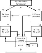
PMC-BiSerial VI Example Block Diagram

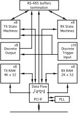
PMC BiSerial III ORB2 version block diagram
PMC Modules require a "carrier" in most cases to adapt them to the system. Dynamic Engineering has carrier solutions for a variety of formats.
PCIe implementations can be done with the PCIeBPMCX1 and PCIeBPMCX2.
PCI implementations can be done with the PCI2PMC and PCIBPMCX2.
cPCI 3U is supported with the cPCIBPMC3U32
cPCI 6U is supported with the cPCIBPMC6U.
PCI-104 is supported with the PCI104p2PMC.
The 34 IO can be configured to support one function, one function replicated several times, or multiple functions. For example: "UART" has 8 UART channels, while the "ORB2" has 8 channels with 4 different functions. A real space saver when you need to have some Manchester to go with your UART and HDLC ports. A partial list of functions implemented in "Channels" includes: Manchester, Miller, SDLC, HDLC, UART, Serial, Parallel, GPIO, COS, Custom, LADEE, NMS, Camera, Ternary, Low Speed, High Speed, Telemetry, Master & Target interactive IO, Adaptive. To support the functions the designs include: memory elements instantiated with FIFO, Dual Port RAM, register files, as well as state-machines, counters, timers, dividers, registers, CRC and Parity generation/checking, software drivers and applications, DMA [direct memory access] and the glue that goes with it. Our designs are all written in VHDL and done in a heirarchy allowing direct porting of different features to create new implementations.
More than 50 customerized versions of the BiSerial family and counting. IP-BiSerial-VI, PMC-BiSerial-VI, PC104p-BiSerial-VI, PCIe-BiSerialDb37, and PMC-BiSerial-6T20 are recommended for new designs.
The hardware has been used to interface with a wide variety of equipment. What do you need to communicate with? Control? Capture data from? Please see the tabs for current and previous portable BiSerial implementations. Descriptions and manuals available. We have been doing custom versions of the BiSerial since 1998 when the IP version was released.
A new custom version can be implemented in a very reasonable time. Typically 2-3 weeks of design time for a medium sized project including the new VHDL set, Windows® or Linux driver, reference software package, and documentation. Examples of the designs performed to date are listed . Please use the tabs to see the current and previous versions of BiSerial.
We can be rapid with our response because the designs are structured to allow channels to be moved in and out to create new design sets. Most designs have a fairly large component of reused "known good" VHDL that we can pull from allowing us to focus on the new functions required for your implementation. You are getting the benefit of many man-years of design and test time with each new version created. Join our high reliability clients by taking advantage of our know-how to help speed your project to completion.
PMC-BiSerial-VI can be used along with a PCIe or other carrier/adapter to use with a variety of system types - PCI, PCIe, PC104p, VPX cPCI, etc. Dynamic Engineering has PMC carriers for PCI, PCIexpress, cPCI, PC104p, and can do custom designs specific to client requirements as well. Please use the handy JAVA pull-down menu at the top of any page to navigate to other Dynamic Engineering products including carriers.
PMCs are independently specificed through VITA for the form factor, connectors and pinouts of the PCI signaling; you can use PMC-BiSerial-VI with any carrier from any vendor that supports standard PMCs. PMC-BiSerial-VI features a 3.3V PCI interface..
It all starts with the PCB [Printed Circuit Board]. Quality design and quality materials are required to meet the strenuous requirements of many of our implementations. You can do the job quickly or you can do the design correctly. We pride ourselves on taking the time to put the extra work into our layouts. The quality goes in before the parts go on. In addition to routing strategy and layer counts, Via size, plating requirements, break-out trace widths, and materials are areas where quality comes into play. The via size and method of trace attachment to the via affect the signal shape and reliability. Using tear-drop trace connections to pads, vias and through hole components enhance the reliability and minimize the impedance discontinuity resulting in a cleaner signal. Calculating the size and quantity of vias to provide adequate copper for proper power distribution and thermal aspects. Working the stack-up to allow larger trace widths for a given impedance provides better vibration endurance. The design has several power planes with sufficient copper weight and coverage to provide the references required for the routing plus the current and voltages needed by the various devices on the board. Since 1998 when the IP BiSerial was introduced, the BiSerial family has enjoyed an excellent track record for reliability.
The PCI interface has a published set of requirements for compliance which restrict length, impedance, loading and other factors. PMC-BiSerial-VI is compliant with the PCI Specification. The IO section has requirements based on the IO type and the purpose for the IO. A very conservative approach has been taken to allow operation with any client requirement. The IO can be LVDS or RS-485. The IO on the connector side is differential with a 100 ohm impedance requirement. Between the FPGA and the tranceivers the IO is single ended. Each IO has separate direction, termination, and data lines to allow complete flexibilty. The design has matched length connections from the FPGA ball to the seating plane of the connector. The lengths are matched to the "mil". The Impedance is controlled and the signals routed with proper spacing to avoid cross talk etc. The other features including memory, PLL, oscillator, and power supplies are implemented within the PCB to exceed the operational requirements for those devices.
The FPGA has internal block RAM which can be configured in a variety of ways. Currently, up to 268 BRAMs can be configured for internal memory support. In addition, the memory can be configured as Dual Port RAM to allow direct addressing and retransmission of repeated patterns.
Sometimes you just need more memory. New with Revision 7 is DDR with 256 Mbytes. The DDR is supported with FPGA based FIFOs and a controller to allow more than one port to use the memory. Internal loop-back is supported. The loop-back test can be used for BIT and for software development. Programmable FIFO flags are supported on both sets of FIFOs. Programmable Almost Full, Programmable Almost Empty, plus Full, Half Full, and Empty. The programmable flags can be set to any depth to allow the software a programmable delay from event to empty or full. The interrupts can be very useful when sending or receiving messages larger than the FIFO size. The interrupts are programmable and provisions are made to allow polling. DMA can be programmed to fill or empty the FIFO with sizes larger than the FIFO size. DMA is hardware controlled to be held off when no data is available or no room is available. Software can set the amount allocated to each function supported by the DDR. With the "Channelized DMA"™ capability and large FIFOs the software application can have reduced interrupt counts to deal with while supporting larger and faster IO transfer rates.
PMC-BiSerial-VI has 34 transceivers which can be used for any combination of input and output functions. Parallel and serial data, multiple channels, and different hand-shaking schemes can be implemented with the quantity of IO on the PMC-BiSerial-VI. RS-485 transceivers support up to 50 Mbps rates. The LVDS transceivers are rated at better than 200 MHz.
The IO is available through either the front panel mounted SCSI III connector or Pn4 or some combination. Each transceiver pair is isolated from the connector with zero ohm resistors. The resistors are mounted front and rear and tied together at each pin to allow for a stub length of 1/16th in. The Connectors are routed from the resistors directly allowing for almost zero stub lengths and the option to connect front or rear IO options. Two banks of transorbs are used to provide signal protection near each of the connectors. Installed bank matched to connector selected.
Clock options are frequently a major factor in embedded designs. Getting the right reference to the right part of the design and allowing for local control of exact frequencies. PMC-BiSerial-VI has a PLL with 4 programmable outputs, reference oscillator, internal DCMs and buffering plus programable dividers instantiated within the VHDL. The PLL can be programmed to "any" fixed frequency, the DCM used to create phase variations, and local dividers to allow on-the-fly channel based frequency changes.
"Channelized DMA"™ is an important feature of the PMC-BiSerial-VI design. With "Channelized DMA"™ you have a separate DMA engine for each transmitter and each receiver within each channel. Each state-machine can be serviced independently with DMA without requiring intervention from the host. Large data transfers can happen between multiple connections while the CPU is off doing something else. In non-channelized designs the CPU will have to intervene each time a different port needs to be serviced. With a channelized approach the hardware takes care of the local arbitration, and eliminates the intervention for better system performance and less latency.
If your situation demands a custom application we will update the Xilinx FPGA and IO components. Send us your timing and we will send you the interface. Please refer to the previously completed "customerized" PMC-BiSerial-VI implementations.
email us your wish list or call today
PMC BiSerial III ORB2 version block diagram
PCIe implementations can be done with the PCIeBPMCX1 and PCIeBPMCX2.
PCI implementations can be done with the PCI2PMC and PCIBPMCX2.
cPCI 3U is supported with the cPCIBPMC3U32
cPCI 6U is supported with the cPCIBPMC6U.
PCI-104 is supported with the PCI104p2PMC.
PMC-BiSerial-VI Features
Size
Std PMC 74mm x 149mm nominal. Low profile components on rear
IO
IO is available via the PMC bezel connector and/or the PMC "user IO" connector Pn4. The differential IO is properly routed with impedance control, pitch, and space plus matched lengths across all of the pairs. 0 ohm resistors are used to isolate the front and rear panel IO to allow single port designs to remove the bus stub to the removed port. Please note that the lower 32 channels [only] are routed to Pn4 due to pin limitations. Differential pairs match Dynamic Engineering PMC Carrier Differential Routing standard to allow high speed [when needed] operation. Up to 50 MHz with RS-485 and up to 200 MHz with LVDS IO types.
Clocks
33 MHz PCI, 50 MHz oscillator ( other frequencies available), 4 programmable PLL inputs, Counters/Dividers/DCM for local clock control.
Interface Types
Custom programmed interfaces are available. Please send us a timing diagram, and we can program one for you. Most interfaces can be adapted from our large library of designs within 2-3 weeks including the updated VHDL, Windows or Linux Driver, reference manuals etc. We can support on-site [ours] integration to help you get your application level software working.
Alternatively choose one of the already completed versions and purchase off-the-shelf. Common requested and implemented interface types include: Manchester, Miller, SDLC, UART, Serial, Parallel, GPIO, COS, Custom, LADEE, NMS, Camera, Ternary, Low Speed, High Speed, Telemetry, Master & Target interactive IO, Adaptive. Mix and Match. Just like but different...
Alternatively choose one of the already completed versions and purchase off-the-shelf. Common requested and implemented interface types include: Manchester, Miller, SDLC, UART, Serial, Parallel, GPIO, COS, Custom, LADEE, NMS, Camera, Ternary, Low Speed, High Speed, Telemetry, Master & Target interactive IO, Adaptive. Mix and Match. Just like but different...
Memory
Spartan 6 - 100 is standard and has 268x1Kx16 BRAM´s to create RAM, FIFO etc., With Rev 7, 256 Mbytes of DDR is included.
Software Interface
Control registers are read-writeable
Windows®, and Linux reference SW and Drivers
Windows®, and Linux reference SW and Drivers
Interrupts
Software programmable interrupts on status, errors, completion of transfer, DMA, FIFO levels, custom events. Status can be polled for non-interrupt driven operation as well.
Power Requirement
3.3V and +5V. The 5V is converted to 2.5, 1.2 and DDR voltages with local DC:DC power supplies for efficient power conversion. 3.3 and 5V rails should be applied together.
LEDs
On rear indicating DDR and 1.2V power supplies are in regulation. Additional LED showing DDR section is locked to reference 100 MHz. (flashes)
Volatility
Reliability
TBD million hours. Bellcore. GB 25c
PMC-BiSerial-VI Benefits
Speed
PMC-BiSerial-VI can offload your CPU and increase system speed. The IO rate is high allowing for system upgrades, replacement of older boards, and relocating processes done in SW to the HW as needed.
Price
System level cost is best when reasonably priced reliable hardware is used and NRE minimized. With PMC-BiSerial-VI, driver support for the carrier and IP level, reference software, history of reliable operation, and fantastic client support your cost per unit and overall costs are attractive.
Ease of Use
PMC-BiSerial-VI is designed to be easy to use. Direct access to all features, aligned registers for larger access types, programmable features to allow personalization for your system. Please download the manuals and see for yourself. Reference software is provided in source form to get you started.
Availability
The -UART model with RS-485 Bezel IO is stocked. Many of the other designs can be implemented with a quick "PCO" to reflash and retest into your configuration. Already completed designs can be ordered with a minimal delay in delivery. New NRE required designs will have some delay to implement, integrate and test. With our on-site manufacturing the production delays are minimized.
PMC Specification Compatibility
PMC-BiSerial-VI is compliant per the VITA PMC/CMC specifications. Tested with PCI and PCIe based carriers. All Dynamic Engineering PMC Modules are compatible with the PCIeBPMCX1, PMC-BiSerial-VI will operate with any PMC specification compliant carrier board.
Part Number: PMC-BiSerial-VI
Ordering Options
- PMC-BiSerial-VI Standard board - with RS485 IO , Industrial temperature components.
- -LVDS Switch to LVDS IO
- -ROHS Use ROHS processing. Standard processing is "leaded"
- -CC Option to add Conformal Coating
- -TSE Include thumb screw extenders to allow mating with Thumb Screw style SCSI cable. Not required for Latch Block Style.
- -XXX See Models section for customized versions and replace XXX with type "UART" for example
PMC-BiSerial-VI Drivers
Software Support for PMC-BiSerial-VI-XXX includes: Windows®, and Linux compliant drivers. VxWorks by special request.
Please see the Driver manuals for the specifics of each type.
Drivers and Reference SW are developed for each type/version of PMC-BiSerial-VI implemented. When custom versions are ordered the NRE will include providing Windows, Linux, and/or VxWorks packages. For off-the-shelf models, select on the manuals tab, the Windows® and Linux SW shown is included with your purchase of the HW. A one-time charge is required for the VxWorks versions. Unsupported SW versions may have an NRE requirement.
Integration support is available. Please contact Dynamic Engineering for this option or download the Technical Support Description from the Company button.
PMC-BiSerial-VI Models
PMC-BiSerial-VI-UART
Customer: ADI, LMCO, Boeing
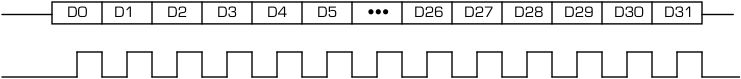
8 UART I/O ports each consisting of RS-485 transmit and receive data. [LVDS is an ordering option]. The UART interface uses a 16x clock to detect received data bits. Received data is filtered with the port reference clock to remove line glitches. The interface can operate at up to 2 Mbits/second using a 32 MHz clock. Reference clock for each port is selectable between the 32 MHz reference and a user programmed PLL frequency. Each UART port has 255 x 32 FIFO for transmit and another 255x32 for receive in addition to Packet Definition FIFOs. DMA support on all channels. 5 modes can be selected per fully independent node: Standard UART (unpacked), Packed, Packetized, Alternate Packetized, and Test. Options for Bezel and Rear IO. Alternate signal/pin definitions to be compatible with Abaco/Radstone PMC-Q1F which is now EOL. See HW manual for details. Option for standard and a modified IO pinout version. -LM13 pinout matches Abaco / Radstone PMC-Q1F. New with this revision is a GPIO parallel port with COS that can selectively replace any UART ports not in service.
UnPacked mode 8 bit data is assumed mimicking standard UART operation
Packed mode 32 bit data is assumed allowing 4 characters to be read/written at a time.
Packetized mode allows for non-LW data lengths, and retains most of the efficiency of LW packing. Odd lengths [non LW boundaries] are loaded with the complete LW´s first then the remainder. The Packet length FIFO is programmed with the length to send. The Packet lengths can be loaded to transmit with minimal HW delay between Packets or with a programmed delay.
Alternate Packetized mode: 3 data bytes per LW with the packet descriptor information built into the 4th byte.
Test mode SW controls the output pattern to allow for programmed errors on certain characters sent.
Programmable timers are available to control the time between packets sent and as a master timer to start new bursts of packets. In addition the Alternate Packet mode supports automatic tristate control and automatic transmit enable/disable to support the packet burst timing. Please see the HW manual for more information.
Download the PMC BiSerial VI UART Hardware manual. This revision adds a programmable GPIO port to use with any unused UART ports.
Download the PMC BiSerial VI UART Windows Driver manual.
Download the PMC BiSerial VI UART Linux Driver manual.
PMC-BiSerial-VI-S311
PMC-BiSerial-S311 has been updated to have 2 ports using the PMC-BiSerial-VI platform. Each port has a programmable clock source, performs serialization and deserialization. Data is stored into separate Tx and Rx FIFO´s with programmable levels for Almost Full and Almost Empty. Programmable interrupt options. 18 bits with automatic ordering to place the start and mode bits in the proper locations while presenting a more logical bit order for SW.
Download the PMC BiSerial VI S311 Hardware manual.
Download the PMC BiSerial VI S311 Win7 manual.
PMC-BiSerial-VI-OSEH
PMC-BiSerial-III-OSEH has been updated to the PMC-BiSerial-VI platform. Each port has a programmable clock source, performs serialization and deserialization. Data is stored into separate Tx and Rx FIFOs with programmable levels for Almost Full and Almost Empty. Programmable interrupt options. The OSEH protocol implemented provides a single transmit and receive channel each consisting of an RS-485 clock and data. The transmitter can use either an external clock reference, or an internal clock reference supplied by the on-board PLL.
Download the PMC-BiSerial-VI-OSEH Hardware manual.
Download the PMC-BiSerial-VI-OSEH Win10 manual.
PMC-BiSerial-VI-HW1
PMC-BiSerial-III-HW1 has been updated to the PMC-BiSerial-VI platform. The HW1 protocol implemented provides 32 Manchester encoded data ports per card. Each port can operate with a selectable frequency, RX or Tx mode, unidirectional or bidirectional. CRC, Manchester, Ready_Busy, and other status provided. Internal Dual Port RAM blocks [512 x 32] used for each of the 32 channels. The 32 port plus 2 additional IO can be used for a parallel port. Bit level programmable for function, Direction, Termination. Option to use I2O or standard interrupts. The reference frequencies can be derived from the on-board oscillator or SW programmable PLL.
Download the PMC-BiSerial-VI-HW1 Hardware manual.
Customer: ADI, LMCO, Boeing
8 UART I/O ports each consisting of RS-485 transmit and receive data. [LVDS is an ordering option]. The UART interface uses a 16x clock to detect received data bits. Received data is filtered with the port reference clock to remove line glitches. The interface can operate at up to 2 Mbits/second using a 32 MHz clock. Reference clock for each port is selectable between the 32 MHz reference and a user programmed PLL frequency. Each UART port has 255 x 32 FIFO for transmit and another 255x32 for receive in addition to Packet Definition FIFOs. DMA support on all channels. 5 modes can be selected per fully independent node: Standard UART (unpacked), Packed, Packetized, Alternate Packetized, and Test. Options for Bezel and Rear IO. Alternate signal/pin definitions to be compatible with Abaco/Radstone PMC-Q1F which is now EOL. See HW manual for details. Option for standard and a modified IO pinout version. -LM13 pinout matches Abaco / Radstone PMC-Q1F. New with this revision is a GPIO parallel port with COS that can selectively replace any UART ports not in service.
Programmable timers are available to control the time between packets sent and as a master timer to start new bursts of packets. In addition the Alternate Packet mode supports automatic tristate control and automatic transmit enable/disable to support the packet burst timing. Please see the HW manual for more information.
Download the PMC BiSerial VI UART Hardware manual. This revision adds a programmable GPIO port to use with any unused UART ports.
Download the PMC BiSerial VI UART Windows Driver manual.
Download the PMC BiSerial VI UART Linux Driver manual.
PMC-BiSerial-VI-S311
PMC-BiSerial-S311 has been updated to have 2 ports using the PMC-BiSerial-VI platform. Each port has a programmable clock source, performs serialization and deserialization. Data is stored into separate Tx and Rx FIFO´s with programmable levels for Almost Full and Almost Empty. Programmable interrupt options. 18 bits with automatic ordering to place the start and mode bits in the proper locations while presenting a more logical bit order for SW.
Download the PMC BiSerial VI S311 Hardware manual.
Download the PMC BiSerial VI S311 Win7 manual.
PMC-BiSerial-VI-OSEH
PMC-BiSerial-III-OSEH has been updated to the PMC-BiSerial-VI platform. Each port has a programmable clock source, performs serialization and deserialization. Data is stored into separate Tx and Rx FIFOs with programmable levels for Almost Full and Almost Empty. Programmable interrupt options. The OSEH protocol implemented provides a single transmit and receive channel each consisting of an RS-485 clock and data. The transmitter can use either an external clock reference, or an internal clock reference supplied by the on-board PLL.
Download the PMC-BiSerial-VI-OSEH Hardware manual.
Download the PMC-BiSerial-VI-OSEH Win10 manual.
PMC-BiSerial-VI-HW1
PMC-BiSerial-III-HW1 has been updated to the PMC-BiSerial-VI platform. The HW1 protocol implemented provides 32 Manchester encoded data ports per card. Each port can operate with a selectable frequency, RX or Tx mode, unidirectional or bidirectional. CRC, Manchester, Ready_Busy, and other status provided. Internal Dual Port RAM blocks [512 x 32] used for each of the 32 channels. The 32 port plus 2 additional IO can be used for a parallel port. Bit level programmable for function, Direction, Termination. Option to use I2O or standard interrupts. The reference frequencies can be derived from the on-board oscillator or SW programmable PLL.
Download the PMC-BiSerial-VI-HW1 Hardware manual.
PMC-BiSerial-VI Previous Revisions
Models designed on PMC-BiSerial, PMC-BiSerial-II, and PMC-BiSerial-III PCBs can be ported and updated to the current PMC-BiSerial-VI PCB retaining the same pinout for ease of use in previously implemented systems. Software Packages can be updated to the current OS revisions. By reusing the initial register map and definitions previous versions of the software can still be used. New features can be added, memory expanded etc.. Updated versions are moved to the Current Models page and include the S311, HW1, and OSEH models. Please contact Dynamic Engineering for this service.
PMC-BiSerial-III
2005 - 2015
These versions can be ported to the current revision of the PMC-BiSerial
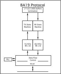
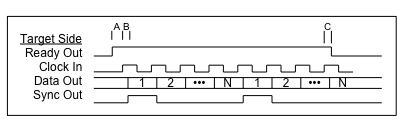
The BA19 implements a Master and a Target interface. Each interface has 8Kx32 FIFO and a dedicated DMA engine. The IO is LVDS, 8 bit parallel Data with Ready, Sync, and Clock. Ready and Clock are used to provide flow control. PLL is programed for rate control. The applications software works with the driver to capture data and store to HDD using DMA.
Download the BA19 Hardware manual
Download the BA19 Windows® Driver manual
The BA23 protocol implemented provides eight UART I/O channels each consisting of RS-485 transmit and receive data. The UART interface uses a 16x clock to detect received data bits. For channels 0-5 the interface can operate at up to 10.4 Mbits/second and uses byte oriented data. Each UART channel has separate Dual Port RAM to allow for retransmit of data. Multiple trigger and operational modes supported. The upper ports 6 and 7 have a 32 bit UART and are supported with FIFO memory. DMA and target access for all channels. Please download the HW manual for the details. This version is a variant of the BAE9 design with the upper channels modified for new funtionality.
Download the BA23 Hardware manual
The BAE9 protocol implemented provides eight UART I/O channels each consisting of RS-485 transmit and receive data. The UART interface uses a 16x clock to detect received data bits. The interface can operate at up to 10.4 Mbits/second. DMA is supported for each channel independently. Each UART channel has separate Dual Port RAM to allow for retransmit of data. Multiple trigger and operational modes supported.
Download the BAE9 Hardware manual
Download the BAE9 Windows® Driver manual for IOCTL based Win7 and Win32 model drivers
Download the BAE9 manual for High Performance Linux Driver
PMC BiSerial III version HW1
The HW1 has been ported to PMC-BiSerial-VI. For older models, use the manuals below. Download the HW1 Hardware manual
Download the HW1 Windows® manual
PMC BiSerial III version HW2
Customer: The Goebel Company
The HW2 version implements 8 channels of the HW1 protocol, plus 24 blocks of Asynchronous or SDLC IO. The SDLC takes 4 blocks per channel and the Asynchronous takes two. Each HW1 channel can operate with a selectable frequency, RX or Tx mode, unidirectional or bidirectional. CRC, Manchester, Ready_Busy, and other status provided. Internal Dual Port RAM blocks [512 x 32] used for each of the 32 blocks. The SDLC channels are programmable for frequency using the PLL. The Asynchronous channels are designed with a UART style protocol. Please see the hardware manual for the details. Revision G or later design shipped unless ordered with -RevF appended to name.
Download the HW2 Hardware manual - RevF FLASH
Download the HW2 Hardware manual - RevG FLASH and later
Download the HW2 Windows® XP manual
Download the HW2 Windows® WDF (7) manual
Download the HW2 Linux; manual
PMC Biserial III version LM5
Customer : Lockheed Martin
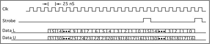
8 channels of half duplex serial interface. Each serial interface channel is supported with clock, strobe, and two data bits. With a 40 MHz serial clock 80 MHz data is effectively transmitted. Each channel is supported with memory in the form of a 1K x 32 FIFO to store transmit data or received data. Each channel is independent and can be programmed to be a transmitter or receiver. The IO is supported with LVDS devices and can be implemented with RS-485 as an option. Programmable interrupts, status bits, and r/w registers make up the programming interface.
Download the LM5 Hardware manual
PMC Biserial III version LM6
Customer : Lockheed Martin
The protocol implemented provides four I/O channels each consisting of LVDS transmit and receive data and clock. The on-board PLL is used to generate the two clocks required for the design. The PLL is programmable, and uses a 40 MHz reference oscillator to generate a wide range of frequencies. The target rates for this design are 10 Mbits/sec for channels zero and one and 62.5 Mbits/sec for channels two and three.
Data for all channels is received MSB first using start and stop bits to separate data words. Channels zero and one send and receive 36-bit words (packets) consisting of two start bits (1´s) a 32-bit data field a parity bit and one stop bit (0) with data changing on the falling edge of the clock (stable on the rising edge). The parity bit is calculated using even parity over the data field. A data frame is terminated with an idle packet consisting of a 36-bit word of all 0´s. When no data is being sent, the data line remains in a 0 state.
Channels two and three use different formats for transmitted and received data. A transmit packet consists of one start bit (1), a 32-bit data field, an odd parity bit and one stop bit (0) for a total of 35 bits. The received data-word is 66 bits long consisting of one start bit (1), a 64-bit data field and one stop bit (1). Each data-frame begins with a sync word in the upper-half of the first data word. If this is not seen, data will still be stored, but a framing error will be latched. Parity is not used on this interface. Both interfaces have data changing on the rising edge of the clock (stable on the falling edge).
Download the LM6 Hardware manual
Download the Windows® Driver manual
PMC BiSerial III version MDS1
Customer: MDS Aero - Canada
The MDS1 protocol implemented provides 4 channel Manchester encoded serial interface. Each channel can operate with a selectable frequency, RX or Tx mode, unidirectional or bidirectional. CRC, Manchester, Ready_Busy, and other status provided. Internal Dual Port RAM blocks [512 x 32] used for each of the channels.
Download the MDS1 manual
Download the MDS1 Linux driver manual
PMC BiSerial III version NASA1
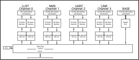
NASA1 is a 4 channel implementation with interfaces for three types of telemetry plus UART and Parallel Ports.
Channel 0 provides the "LADEE - LLST" interface supported with DMA and 8Kx32 of FIFO in each direction. PLLA is used to set the TX reference frequency typically 40 Mhz. The interface is LVDS.
Channel 1 provides the "NMS" interface supported with DMA and 8Kx32 of FIFO in each direction. PLLB is used to set the TX reference frequency typically 1-10 Mhz. The interface is RS-422 / RS-485.
Channel 2 provides the "UART" interface supported with DMA and 1Kx32 of FIFO in each direction. PLLC is used to set the reference frequency typically 14.7456 Mhz., which is further divided within the channel to provide all of the standard baud rates. The interface is RS-422 / RS-485.
Channel 3 provides the " Uplink and Downlink" interface supported with DMA and 1Kx32 of FIFO in each direction. Manchester encoded. PLLD is used to set the reference frequency typically 8 Mhz., which is further divided within the channel to provide the 8x and 2x clocks used for the Downlink and Uplink respectively. The rates are divided separately allowing for asymmetrical operation. The interface is RS-422/RS-485.
The remaining IO are used for a 14 bit parallel port with bit level direction control. RS-422/ RS-485 IO.
Download the NASA1 Hardware manual
Download the NASA1 Windows® driver manual
PMC BiSerial III version NG8
Customer: Northrop Grumman
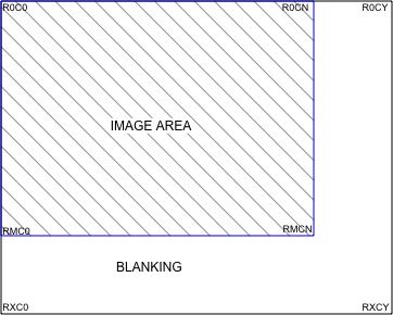
The NG8 design features 2 channels with transmit or receive "camera protocol". Each channel has Clock, HREF, VREF, BadPixel, and Pixel data [11-0]. "Channelized DMA"™ is used along with 133K x 32 FIFO to provide continuous operation. The transmit rate is selected with a PLL allowing for custom user frequencies. The image size is programmable. Blanking and active image areas are programmable. Interrupts, status and error checking. RS-485 is used for the IO.
Download the NG8 Hardware manual
Download the NG8 Windows® driver manual
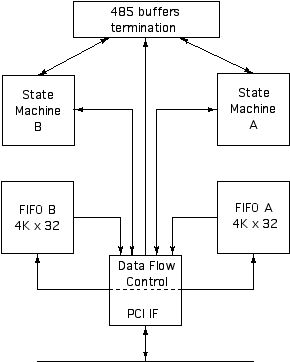
PMC BiSerial III version ORB2
Customer: Orbital
The ORB2 design features multiple protocols: 2 channels each of Ternary, LS, HS, and Telemetry data. Each channel can operate with a selectable frequency, Rx or Tx mode, status provided. Internal FIFO is provided 4Kx32 for Rx or Tx on the Ternary and LS ports. A combination of internal 4K x 32 and external 128Kx32 are provided on the HS ports. Programmable lengths and delays between packets sent. Programmable polarity on clocks, and strobes. Programmable bit order. Programmable frequency. Interrupts, status and error checking. RS-485 is used for the Ternary, LS and Telemetry ports. LVDS is used for the HS ports.
Download the ORB2 Hardware manual
Download the ORB2 Windows® driver manual
PMC BiSerial III version OSEH
OSEH has been ported to the PMC-BiSerial-VI. For older models, use the manuals below.

Download the OSEH Hardware manual
Download the OSEH Driver manual
PMC BiSerial III version RL1
Customer: restricted
The RL1 protocol implemented provides eight UART I/O channels each consisting of RS-485 transmit and receive data. The UART interface uses a 16x clock to detect received data bits. The interface can operate at up to 10 Mbits/second using a 160 MHz clock. DMA is supported for each channel independently. Each UART channel has 1K x 32 FIFO for transmit and another 1Kx32 for receive. This design is replaced with the -UART option. See the current designs tab.
Download the RL1 Hardware manual
Download the RL1 Windows® XP Driver manual
Download the RL1 Windows® 7 Driver manual
PMC BiSerial III version UART
UART has been ported to the PMC-BiSerial-VI . For older models, use the manuals below.
Download the PMC BiSerial III UART Hardware manual
PMC BiSerial III version SDLC
Customer: Boeing
8 Channels of full duplex SDLC [Synchronous Data Link Control] with internal or external clock reference. Software/PLL rate programability. Separate Tx and Rx 4K byte Dual Port RAM circular buffers. Interrupts [programmable] available for end of each message frame transmitted, at the end of all message frames transmitted, at the end of each received message frame, when an abort character is received. Masked status is available to allow operation in polled mode. I2O interrupts are also available. Please note: SDLC is a subset of HDLC and can be used in HDLC systems using byte delineated data. Linux and Windows driver/UserApplication support. The SDLC design has been ported to ccXMC-Serial and upgraded to HDLC. This design can be ported back to PMC-BiSerial-VI.
Download the PMC SDLC Hardware manual
Download the PMC SDLC Win7 manual
Download the PMC SDLC Linux Driver manual
PMC-BiSerial-II
2002 - 2005
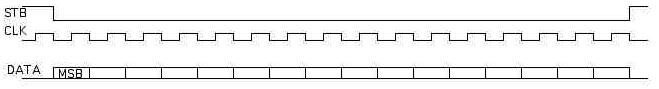
The standard timing [-IO] uses the clock and strobe to transmit and to receive the data. Data is shifted to the next bit on the falling edge and valid of the rising edge of the clock. The Set-up and hold are approximately 50/50 for a very stable interface. The clock edge can be reversed, the strobe can be made to be active high, the data width can be changed, the bit order can be changed etc. Frequently parity or other error correction provisions are added. If the standard or one of the customer specific protocols will work for you - fantastic - and if not please let us know what you need and we can implement it for you.
These versions can be ported to the current revision of the PMC-BiSerial
Customer: Navy
The Nvy1 protocol implemented provides redundant Manchester encoded data inputs and outputs. -128 FIFO option utilized. Additional two UARTs provided.
PMC-BiSerial-II-NVY1 Manual
BiSerial II version NG1
Customer: Northrop Grumman
The NG1 protocol implemented provides two synchronous and two asynchronous ports plus clock distribution and status. Windows driver available.
PMC-BiSerial-II-NG1 User manual
PMC-BiSerial-II-NG1 Driver manual
BiSerial II version PS2
Customer: Photo-Sonics Inc
The PS2 version implemented provides 8 synchronous ports plus an 8 bit parallel port with COS input capability. The synchronous ports are configured with 4 Transmit and 4 Receive. Programmable clock rate. Data, Clock and Strobe interface. Lsb first data. each channel has 128x32 FIFO using internal block RAM. Engineering Kit available.
PMC-BiSerial-II-PS2 User manual
PMC-BiSerial
2000 - 2002
These versions can be ported.
Customer: Northrop Grumman
Provide an interface to legacy radar systems using the S-311 protocol [data transfer between sub-systems within the radars]. Windows7 driver available for this version.
PMC-BiSerial version BAE1
Customer: BAE
The BAE1 protocol implemented provides a 40 bit serially transmitted Real Time Clock programmable as a master or target. In target mode a local copy of the clock is kept for time-tagging local processes. When the master transmission is received the local clock is updated to stay in sync through-out the system. Industrial Temp.
Windows® Driver Available
PMC-BiSerial version BA1
Customer: Boeing
The BA1 protocol implemented provides a Serial Data Analyzer function used for
network snoopingin a test environment. -32 FIFO option.
BiSerial version Nvy1
Customer: Navy
The Nvy1 protocol implemented provides Manchester encoded data inputs and outputs. -32 FIFO option
BiSerial version PS1
Customer: Photo Sonics
Four Transmit and no Receive channels. 5 MHz transmit rate. 16K Fifo channel 0, 4 x 32 FIFO channels 1-3. Reference clock out. Reference strobe on channel 0. LSB first. Fixed synchronization pattern on channels 1-3. FIFO based synchronization pattern on channel 0.