Made in USA
The Embedded Solutions Experts
PCI-ASCB
Dual Redundant ASCB plus PMC Adapter/Carrier
Order This Item
Please contact sales@dyneng.com for this item.PCI-ASCB Description
- 1/2 length PCI device with PMC position
- 2 dual redundant ASCB ports supporting type D [Manchester] and eASCB [8B10B] modes
- Dual Port RAM with DMA support to store messages for transmission and reception.
- Built in power supplies to support PMC and ASCB function
- Transparent and non-Transparent operation supported. Local PrPMC can be used to manage data or via host computer
- Temperature sensor
- 1 year warranty standard. Extended warranty available.
- Extended [Industrial] Temperature standard.
- ROHS and Standard processing available
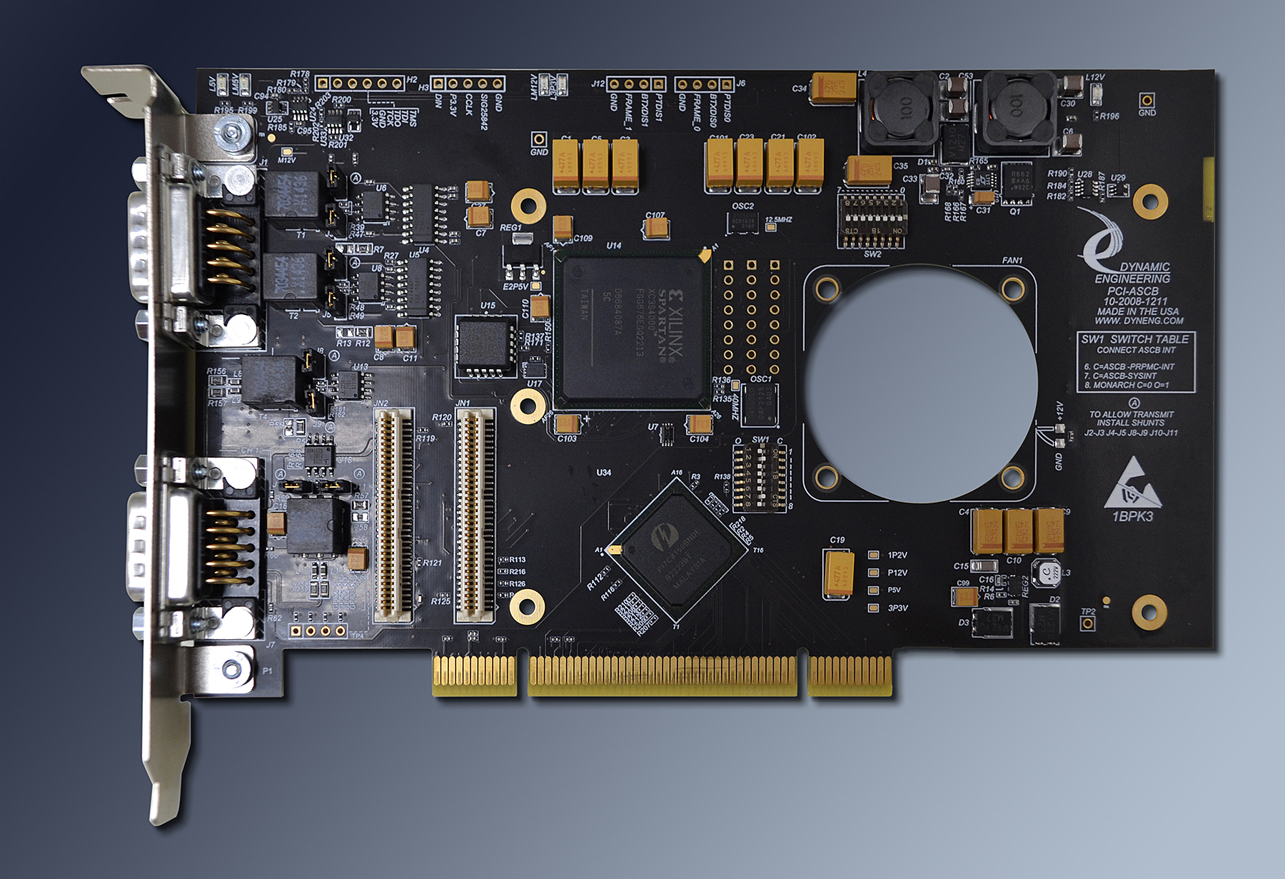
PCI-ASCB (Avionics Standard Communications Bus) Bridge based PCI and PMC Compatible Adapter Carrier with Dual Redundant ASCB Function.
PCI-ASCB provides the ability to install one PMC card into a standard PCI slot while providing Dual Redundant ASCB. Types D and Enhanced are supported. The channels are independent allowing any combination of D and Enhanced processing. The primary and redundant do need to use the same protocol. The ASCB design is done within an FPGA to allow for other applications. The current design is Dual Port RAM based with circular buffers implemented to transfer data from the local CPU to the IO port and vice-versa.
The base ASCB design incorporates a master timer used to coordinate when transmissions will take place. The Software communicates with the transmit state-machine via address pointers and bit level commands stored into the RAM. The RAM is split into 4 sections to cover the two receivers and two transmitters. The RAM is managed as a circular buffer with global controls to allow the software to restart from a known location etc. Software can pre-pack messages to be sent and the hardware will automatically wait for the programmed time, then send the packets with proper gap, pre and post ambles plus CRC processing. The interpacket gap defaults to the ethernet standard and is programmable to allow for test.
The PMC slot can be used with a standard Target PMC device or with a PrPMC. The interrupts can be routed [dipswitch option] between the PrPMC and ASCB function or to the PCI host. A PrPMC can be used for local "real time" processing. Please note that the PMC bezel is mounted inboard on this carrier. Front panel IO from the PMC will be internal to the PC. Most other Dynamic Engineering carriers have the PMC connector mounted through the PCI bezel. Pn4 IO can be used for Ethernet support via the ASCB bezel.
The ASCB or user function is provided through two DB-9 connectors. Each connector has primary and redundant IO plus disables and a frame marker reference. The signals for transmit originate within the FPGA, are buffered by RS-485 compliant driver and isolated from the system with a 10/100 transformer. On the card side of the transformer a separate receiver is connected with the output routed to the FPGA. ASCB cabling has a 62 ohm impedance, PCI-ASCB matches the impedance with stub resistors.
Internal same channel loop-back is available including all components except for the transformer. The transmit side has shunts to allow positive isolation for cases where the transmitter must not become activated - for example acting as a "bus snooper". Software also has control over the transmit enable via a master enable, and the state-machine associated with transmission.
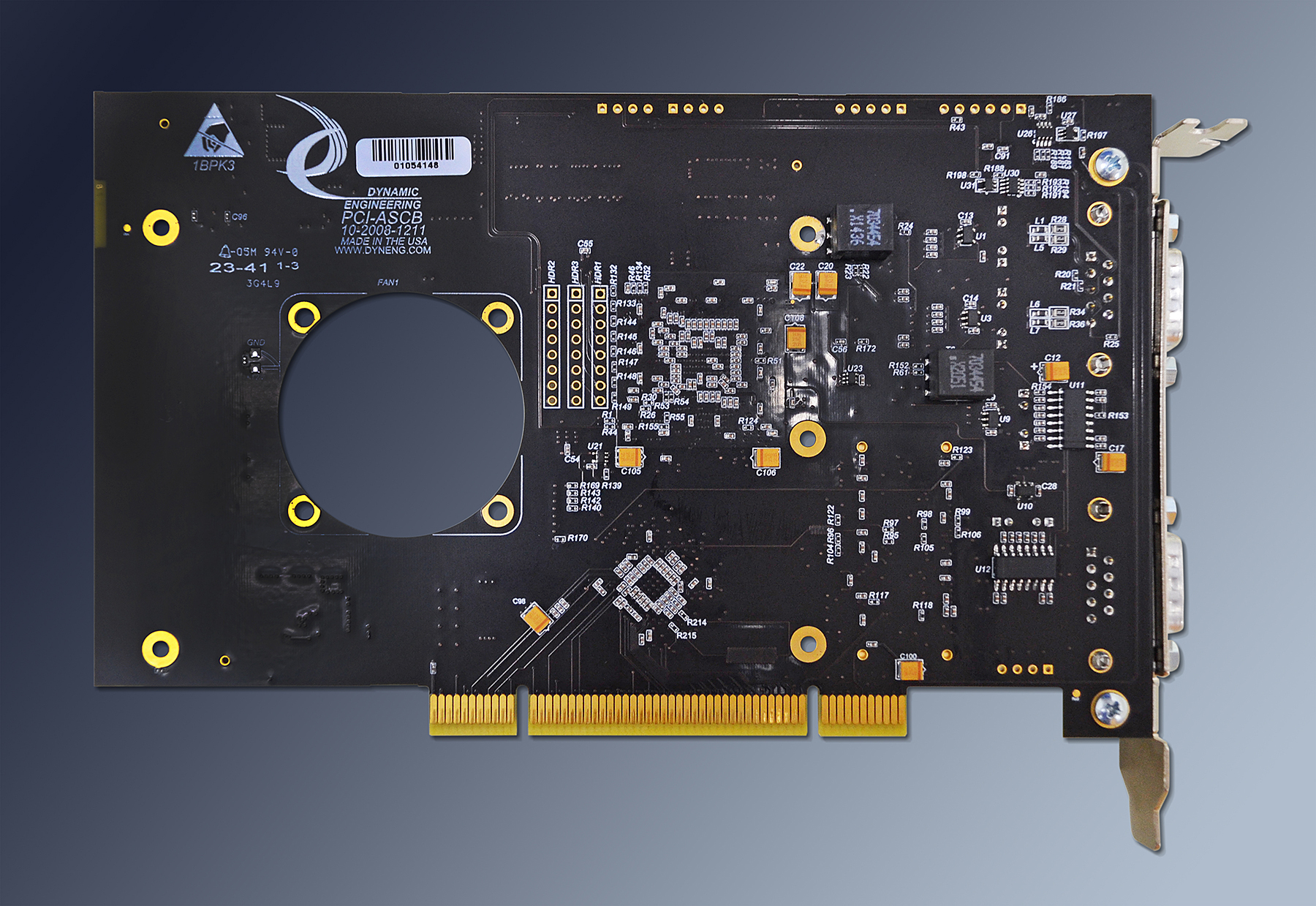
For superior performance PCI-ASCB has a cooling cutout for increased airflow to the PMC. If your installed PMC requires a fan you can order the PCI-ASCB-FAN to have a fan mounted to your PCI-ASCB. "Zero Slot Fan"™ technology is used, allowing use with standard PMC heights and legal for single slot PCI operation.
The PCI bus is interconnected to the PMC via a 32 bit 33 MHz bridge. The bridge allows the PCI bus to operate with different parameters than the PMC card - for example the PCI bus can operate at 66 MHz with 64 bit data and the PMC with 33 mhz and 32 bit data. The buffering within the bridge will take care of the rate and data matching. The local side is set to 33 Mhz based on the ASCB capabilities. The PMC is connected to the bridge with a 32 bit path.
The voltage definitions are buffered between the PCI and PMC buses. The PCI VIO automatically defines the reference levels for the primary side of the bridge. The secondary side of the bridge is set to 3.3V operation for the PMC/prPMC and ASCB functions.
The bridge is located near the PCI "gold fingers" and routed with PCI specification compliant traces for impedance and length to insure that multiple PCI-ASCB cards can be installed onto the same PCI bus stub.
The PCI ±12V, 5V and 3.3V is routed to the PMC slot with voltage planes. High power consumptions PrPMCs are supported. A fan is recommended for high current models.
The PMC JTAG connections are routed to a header. The header is configured to for discrete connections. Add "-JTAG" to your part number for the PMC JTAG header.
PCI-ASCB provides the ability to install one PMC card into a standard PCI slot while providing Dual Redundant ASCB. Types D and Enhanced are supported. The channels are independent allowing any combination of D and Enhanced processing. The primary and redundant do need to use the same protocol. The ASCB design is done within an FPGA to allow for other applications. The current design is Dual Port RAM based with circular buffers implemented to transfer data from the local CPU to the IO port and vice-versa.
The base ASCB design incorporates a master timer used to coordinate when transmissions will take place. The Software communicates with the transmit state-machine via address pointers and bit level commands stored into the RAM. The RAM is split into 4 sections to cover the two receivers and two transmitters. The RAM is managed as a circular buffer with global controls to allow the software to restart from a known location etc. Software can pre-pack messages to be sent and the hardware will automatically wait for the programmed time, then send the packets with proper gap, pre and post ambles plus CRC processing. The interpacket gap defaults to the ethernet standard and is programmable to allow for test.
The PMC slot can be used with a standard Target PMC device or with a PrPMC. The interrupts can be routed [dipswitch option] between the PrPMC and ASCB function or to the PCI host. A PrPMC can be used for local "real time" processing. Please note that the PMC bezel is mounted inboard on this carrier. Front panel IO from the PMC will be internal to the PC. Most other Dynamic Engineering carriers have the PMC connector mounted through the PCI bezel. Pn4 IO can be used for Ethernet support via the ASCB bezel.
The ASCB or user function is provided through two DB-9 connectors. Each connector has primary and redundant IO plus disables and a frame marker reference. The signals for transmit originate within the FPGA, are buffered by RS-485 compliant driver and isolated from the system with a 10/100 transformer. On the card side of the transformer a separate receiver is connected with the output routed to the FPGA. ASCB cabling has a 62 ohm impedance, PCI-ASCB matches the impedance with stub resistors.
Internal same channel loop-back is available including all components except for the transformer. The transmit side has shunts to allow positive isolation for cases where the transmitter must not become activated - for example acting as a "bus snooper". Software also has control over the transmit enable via a master enable, and the state-machine associated with transmission.
For superior performance PCI-ASCB has a cooling cutout for increased airflow to the PMC. If your installed PMC requires a fan you can order the PCI-ASCB-FAN to have a fan mounted to your PCI-ASCB. "Zero Slot Fan"™ technology is used, allowing use with standard PMC heights and legal for single slot PCI operation.
The PCI bus is interconnected to the PMC via a 32 bit 33 MHz bridge. The bridge allows the PCI bus to operate with different parameters than the PMC card - for example the PCI bus can operate at 66 MHz with 64 bit data and the PMC with 33 mhz and 32 bit data. The buffering within the bridge will take care of the rate and data matching. The local side is set to 33 Mhz based on the ASCB capabilities. The PMC is connected to the bridge with a 32 bit path.
The voltage definitions are buffered between the PCI and PMC buses. The PCI VIO automatically defines the reference levels for the primary side of the bridge. The secondary side of the bridge is set to 3.3V operation for the PMC/prPMC and ASCB functions.
The bridge is located near the PCI "gold fingers" and routed with PCI specification compliant traces for impedance and length to insure that multiple PCI-ASCB cards can be installed onto the same PCI bus stub.
The PCI ±12V, 5V and 3.3V is routed to the PMC slot with voltage planes. High power consumptions PrPMCs are supported. A fan is recommended for high current models.
The PMC JTAG connections are routed to a header. The header is configured to for discrete connections. Add "-JTAG" to your part number for the PMC JTAG header.
PCI-ASCB Features
Size
Half length PCI card.
PMC Compatible Slots
1 PMC slot provided..
Clocks
PCI primary bus can operate at 66 or 33 MHz. Secondary side set to 33 MHz.
Access Width
Standard PCI byte lanes supported for byte, word, and long access dependent on installed PMC. 32 bit operation from either bus supported by bridge.
Access Frequency
Bridge supports 66 or 33 MHz operation.
Software Interface
Industry Standard 21154 Bridge register definitions. The bridge does not require any user set-up. PMC register definitions as defined by installed hardware. ASCB interface consists of Dual Port RAM and registers. All registers are read-write [other than status]. DMA or direct read-write accesses. Separate control, status and memory for each channel.
Interrupts
INTA, INTB, INTC, INTD routed to PCI connector. Most PMC's use one interrupt level [INTA]. Interrupts have inter-connect capability to allow PrPMC to handle ASCB interrupt instead of Host processor.
Power
+5V, +12V, -12V, +3V supplied to (Pr)PMC.
VIO
Primary side set by PCI bus. Secondary side set to 3.3V.
Thermal
PCI-ASCB has a cut-out to support increased airflow over the PMC component side. Optional ‟Zero Slot Fan”™ available.
IO Interface
PMC Front Bezel IO supported internal to chassis. Jn4 ‟user IO” Dual redundant ASCB IO Type D and Type E [Enhanced Mode] supported with two DB9 connectors at bezel.
Specification
PCI, PMC specification compliant
LED's
+3V, +5V, +12V, -12V and Busmode 1 [PMC present].
DIP Switches
two - 8 position switches are provided to allow for configuration control, and to select the primary and secondary clocking options.
JTAG
The PMC JTAG connections are tied to a labeled header. Optionally installed "-JTAG"
PCI-ASCB Benefits
Speed
PCI-ASCB offers PCI speeds on the primary and PMC slot sides. DMA is supported with a multi-channel DMA controller designed into the ASCB interface. The base rate on the ASCB IO side is 10(D) 20 (E) MHz. Alternate frequencies can be used.
System Cost
Add your PrPMC to PCI-ASCB for a single slot solution. A single PC can support multiple PCI-ASCB interface cards for alow cost multi-point solution. Reuse software you have already developed on the PrPMC and add the ASCB functions. Windows drivers are available from Dynamic Engineering. A linux solution is also available from The Goeble Company. Quantity discounts are available on the hardware.
Ease of Use
The ASCB function is controlled via dual port memory and direct mapped registers. Each port has separate memory and status. DMA is supported as well as direct read and write accesses. A windows driver is available to use for System CPU based interfaces. A Linux driver is available for PrPMC based applications. The optional use PMC/PrPMC site is "plug and play". The Bridge can be configured with the user switches on board, which eliminates any requirement for special software for the bridge itself. The board comes configured for a 66 MHz capable primary bus and 33 MHz secondary bus. In most cases, the switches can be left with the factory settings. The manual contains clear directions for switch options. The engineering kit provides a good starting point for a new user.
Availability
We build PCI-ASCB to order. With our in-house manufacturing capabilities short lead times result. Send in your quote request and we can provide current pricing and lead time based on your order requirements. sales@dyneng.com
Size
PCI-ASCB is a half length PCI board, which conforms to the PCI mechanical and electrical specifications. Eliminate mechanical interference issues. PCI-ASCB can be used in all full and half-length PCI compliant slots. With the PMC Bezel IO connector in use, a full length slot will likely be required.
PMC Compatibility
PCI-ASCB is PMC compliant per the IEEE 1386 specification. All Dynamic Engineering PMC Modules are compatible with the PCI-ASCB. All other PMC Modules that are compliant with the PMC specification are compatible with the PCI-ASCB.
PCI Compatibility
PCI-ASCB is PCI compliant. The PCI-ASCB can be expected to work in any PCI compliant backplane. The PCI-ASCB has been tested in multiple backplanes.
Part Number: PCI-ASCB
Ordering Options
- PCI-ASCB Standard board - base version (PCI-ASCB with standard processing [leaded solder\. Add any of the following build options after the PN as shown below:
- -ROHS Use ROHS processing. Standard processing is ""leaded"
- -JTAG Add JTAG header to connect to PMC slot JTAG signals.
- -CC Option to add Conformal Coating
- -FAN() for a pre-installed fan to maximize cooling and functionality of your PrPMC card. The standard fan is the "Zero Slot Fan"™
- R For fans blowing to the rear onto the component side of the card below, replace the "X" above with "R"
- F For fans blowing to the front onto the solder side of the card above, replace the "X" above with "F"
PCI-ASCB Drivers
Software Support for PCI-ASCB includes: Windows® 10 driver
Please see the Driver manuals for the specifics of each type.
ASCB Software Package Windows®
Integration support is available. Please contact Dynamic Engineering with any questions or requests regarding drivers.
Please see the Driver manuals for the specifics of each type.
ASCB Software Package Windows®
Integration support is available. Please contact Dynamic Engineering with any questions or requests regarding drivers.
PCI-ASCB Manuals
ASCB Hardware Manual Memory Map, Bit Map, Connector Pinout, theory of operation.
Download the ASCB Statement of Volatility
Download the ASCB Statement of Volatility