Made in USA
The Embedded Solutions Experts
PC/104p-BaseBoard
PCI-104 and PC104p Compatible
Order This Item
Please contact sales@dyneng.com for this item.PC/104p-BaseBoard Description
- Locations for Power Supply and PC104p stack.
- FPGA with PCI bus to provide on-board interfaces
- OptoISO inputs and outputs, A/D, D/A
- ARINC 429, UART[RS-485]
- 1 year warranty standard. Extended warranty available.
- Extended [Industrial] Temperature standard.
- ROHS and Standard processing available
PC104p-BaseBoard was designed as a quick turn project in 2005. At this point some components would need to be updated for production as well as drivers brought up to current standards. The description is provided to show what we could do almost 20 years ago in a short time [delivered in about 3 months from hearing about the requirement]. Dynamic Engineering features integrated Engineering and Manufacturing capabilities. With the engineering staff working closely with the manufacturing staff we are able to create new or modified designs rapidly and to execute on those designs with the FAI and production process. See the Embedded Design and Manufacturing descriptions under "Company".
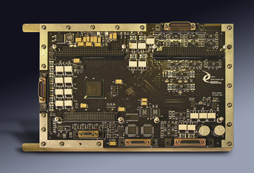
The BaseBoard is part of the PC/104 Module family of modular I/O components by Dynamic Engineering. The BaseBoard is used to integrate a PCI-104 or PC/104p stack with the power supply, 35 Optocoupled Inputs, 37 Optocoupled Outputs, 2 UART - RS-485 ports, 2 ARINC 429 - TX/RX, 4 ADC Ports, and 4 DAC Ports comprize the onboard feature set of the BaseBoard design. The Right hand PC104 slot is designed to be occupied by the Power Supply module which accepts 28V and supplies the standard PC104 voltages on the ISA connector. The left hand slot in the figure above is used to add a PCI-104 or PC/104p stack. The stack will include the system CPU. The BaseBoard occupies slot position 0.
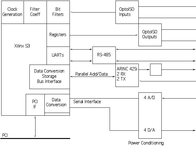
BaseBoard Block Diagram
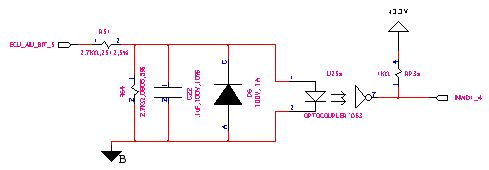
Optical Isolated input circuit
The input signal when high will turn on the LED of the optocoupler and drive the received bit to the Xilinx. The optocouplers are all in this basic arrangement but with some variations for the reference input voltage to match the type of input being measured. The receiver inverts the data as it operates as an open-drain device. The Xilinx inverts the input bits to compensate. When the LED is turned on the status bit for the unfiltered data will be "1".
Within the Xilinx the data is sampled at a programmable rate. The input bits are arranged in "words". Each word has a separate programmable clock. Each bit has a separate control register to program the filter to look for active high, active low, Change of state etc. The circuits are designed to operate in a noisy environment and use hysteresis to help. The filter has a programmable threshold for a low and high value. The values are compared with an up-down counter to determine if the bit should be declared to be a "1" or a "0". The counter acts as accumulator. The hysteresis comes from staying in the "0" state until the counter is into the "1" state and vice-versa.
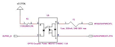
Optical Isolated output circuit
The Optocoupled outputs are controlled with registers within the Xilinx. The outputs are organized as "words". When the bit is set the open drain IO is driven low to turn on the optocoupler. With the LED turned on the opto isolated FET is turned on and the output connected. Some of the switches are configured to be high side and some low side. Some have fuse protection and some have resistor coupling depending on the requirements of the external circuit.
The ARINC 429 interface is made up of two sets of ARINC 429 compatible interface chips. Each set has a controller with a pair of built in receivers and a separate transmitter buffer. One receiver and one transmitter are connected from each chip set to connectors. The Xilinx is tied to both receiver channels.
The PCI bus is 32 bits and the ARINC devices are 16. The PCI bus is much faster than the local bus to the ARINC chips. The Xilinx takes care of converting 32 bit TX data to 16 bit writes and the timing required to load the devices. The ready bit can be used to determine when the next data can be written. When data is available to read from the device the Xilinx retrieves it and stores it before telling the CPU that data is ready to allow the CPU to retrieve the data in one read without added delays accessing the ARINC devices.
There are 4 A/D and 4 D/A provided. Each of the devices is 16 bits and 200 Khz rated for operation. The devices are separately interfaced to allow individual or parallel operation depending on the requirements. Each A/D and D/A has power filtering in the form of a filter bead and added capacitors for improved performance. The Analog channels have a voltage divider capability [resistor positions] designed into the BaseBoard to allow for out of range voltage measurements.
The Xilinx provides two UART circuits. The UARTs operate in half-duplex mode and have programmable baud, parity, and stop bit capabilities. A pair of RS-485 transceivers convert between the single ended Xilinx signals and the differential external IO standard. The channels are programmed to come up as receivers and can become transmitters under software control. The two channels could be combined to make one full-duplex channel should that be required.
The PC/104p-BaseBoard is designed to be rugged. The board layout features high current 2 oz copper and heavy tracewidths for the opto-coupled IO. The MDM connectors are designed to operate under vibration loading. The BaseBoard has a low power dissipation and can be conductively cooled or convection used. An internal isolated shield plane is exposed at the board edges for mounting to the chassis for cooling and electrical purposes. The parts are rated for industrial operation or better [-40 - +85C]. The PC/104p-BaseBoard comes humisealed and can be used in condensing environments.
The BaseBoard is part of the PC/104 Module family of modular I/O components by Dynamic Engineering. The BaseBoard is used to integrate a PCI-104 or PC/104p stack with the power supply, 35 Optocoupled Inputs, 37 Optocoupled Outputs, 2 UART - RS-485 ports, 2 ARINC 429 - TX/RX, 4 ADC Ports, and 4 DAC Ports comprize the onboard feature set of the BaseBoard design. The Right hand PC104 slot is designed to be occupied by the Power Supply module which accepts 28V and supplies the standard PC104 voltages on the ISA connector. The left hand slot in the figure above is used to add a PCI-104 or PC/104p stack. The stack will include the system CPU. The BaseBoard occupies slot position 0.
BaseBoard Block Diagram
Optical Isolated input circuit
The input signal when high will turn on the LED of the optocoupler and drive the received bit to the Xilinx. The optocouplers are all in this basic arrangement but with some variations for the reference input voltage to match the type of input being measured. The receiver inverts the data as it operates as an open-drain device. The Xilinx inverts the input bits to compensate. When the LED is turned on the status bit for the unfiltered data will be "1".
Within the Xilinx the data is sampled at a programmable rate. The input bits are arranged in "words". Each word has a separate programmable clock. Each bit has a separate control register to program the filter to look for active high, active low, Change of state etc. The circuits are designed to operate in a noisy environment and use hysteresis to help. The filter has a programmable threshold for a low and high value. The values are compared with an up-down counter to determine if the bit should be declared to be a "1" or a "0". The counter acts as accumulator. The hysteresis comes from staying in the "0" state until the counter is into the "1" state and vice-versa.
Optical Isolated output circuit
The Optocoupled outputs are controlled with registers within the Xilinx. The outputs are organized as "words". When the bit is set the open drain IO is driven low to turn on the optocoupler. With the LED turned on the opto isolated FET is turned on and the output connected. Some of the switches are configured to be high side and some low side. Some have fuse protection and some have resistor coupling depending on the requirements of the external circuit.
The ARINC 429 interface is made up of two sets of ARINC 429 compatible interface chips. Each set has a controller with a pair of built in receivers and a separate transmitter buffer. One receiver and one transmitter are connected from each chip set to connectors. The Xilinx is tied to both receiver channels.
The PCI bus is 32 bits and the ARINC devices are 16. The PCI bus is much faster than the local bus to the ARINC chips. The Xilinx takes care of converting 32 bit TX data to 16 bit writes and the timing required to load the devices. The ready bit can be used to determine when the next data can be written. When data is available to read from the device the Xilinx retrieves it and stores it before telling the CPU that data is ready to allow the CPU to retrieve the data in one read without added delays accessing the ARINC devices.
There are 4 A/D and 4 D/A provided. Each of the devices is 16 bits and 200 Khz rated for operation. The devices are separately interfaced to allow individual or parallel operation depending on the requirements. Each A/D and D/A has power filtering in the form of a filter bead and added capacitors for improved performance. The Analog channels have a voltage divider capability [resistor positions] designed into the BaseBoard to allow for out of range voltage measurements.
The Xilinx provides two UART circuits. The UARTs operate in half-duplex mode and have programmable baud, parity, and stop bit capabilities. A pair of RS-485 transceivers convert between the single ended Xilinx signals and the differential external IO standard. The channels are programmed to come up as receivers and can become transmitters under software control. The two channels could be combined to make one full-duplex channel should that be required.
The PC/104p-BaseBoard is designed to be rugged. The board layout features high current 2 oz copper and heavy tracewidths for the opto-coupled IO. The MDM connectors are designed to operate under vibration loading. The BaseBoard has a low power dissipation and can be conductively cooled or convection used. An internal isolated shield plane is exposed at the board edges for mounting to the chassis for cooling and electrical purposes. The parts are rated for industrial operation or better [-40 - +85C]. The PC/104p-BaseBoard comes humisealed and can be used in condensing environments.
PC/104p-BaseBoard Features
Size
Custom board size. Standard PC/104p or PCI-104 sites. Outline drawing available upon request.
IO Speeds
Dual Speed ARINC 429, up to 200 Khz [ADC and DAC], up to 1 MHz on the UART ports.
Clocks
Programmable clocks for Optolsolated inputs, UART, ARINC ports.
PCI
32/33 operation is supported for the PC/104p or PCI-104 stack.
Software Interface
Read-write ports to control interfaces.
Interrupts
Software programmable interrupts on all active circuits plus status to operate in polled mode.
Ports
35 Optocoupled inputs, 37 Optocoupled outputs, 2 UART - RS-485 ports, 2 ARINC 429 - TX/RX, 4 ADC Ports, and 4 DAC Ports.
Power
Slot provided to add PC/104 ISA routed power supply card. Local regulation for 3.3, 2.5, and 1.25V. Power routed to PCI-104/PC104p connectors to support the stack. High current internal planes utilized.
PC104p-BaseBoard Benefits
Size & Speed
The BaseBoard design integrates the FPGA controlled features and stack support to allow off-the-shelf components to be mixed with the special requirements. The FPGA connection is direct from the PCI bus to the CPU allowing for fast communications and control. The stack modules are also direct connected to provide a path through those components. The combination leads to a compact, mechanically strong package.
Price
System level cost is best when reasonably priced reliable hardware is used and NRE minimized. With PC104p-BaseBoard, driver support for the BaseBoard and Stack, reference software, history of reliable operation, and fantastic client support your cost per unit and overall costs are attractive.
Ease of Use
PC104p-BaseBoard is easy to use. A point and shoot user interface to the built in features sites. Please download the manuals and see for yourself. Reference software is provided in source form to get you started.
Availability
This is a built to order item. Dynamic Engineering has in house manufacturing capabilities for shorter lead times
PC104p Specification Compatibility
PC104p-BaseBoard is PC104p compliant per the consortium specification. All Dynamic Engineering PCI-104 Modules are compatible with the PC104p-BaseBoard. All other PC104p Modules which are compliant with the specification can be expected to work.
Part Number: PC/104p-BaseBoard
Ordering Options
- PC/104p-BaseBoard Standard board - Add any of the following build options after the PN as shown below:
- -ROHS Use ROHS processing. Standard processing is "leaded"
- -CC Option to add Conformal Coating
PC104p-BaseBoard SoftWare
Software Support for PC104p-BaseBoard includes: drivers and reference SW for the built in features. This project as mentioned above is from 2005. Any new versions will require updated SW as teh OS in use at that time have moved on.
Integration support is available. Please contact Dynamic Engineering for this option or download the Technical Support Description from the Company button.
Integration support is available. Please contact Dynamic Engineering for this option or download the Technical Support Description from the Company button.
PC/104p-BaseBoard Manuals
Click on the link to Download selected manuals in PDF format.
PC104p-BaseBoard Hardware manual for PC/104p-BaseBoard.
PC104p-BaseBoard Hardware manual for PC/104p-BaseBoard.